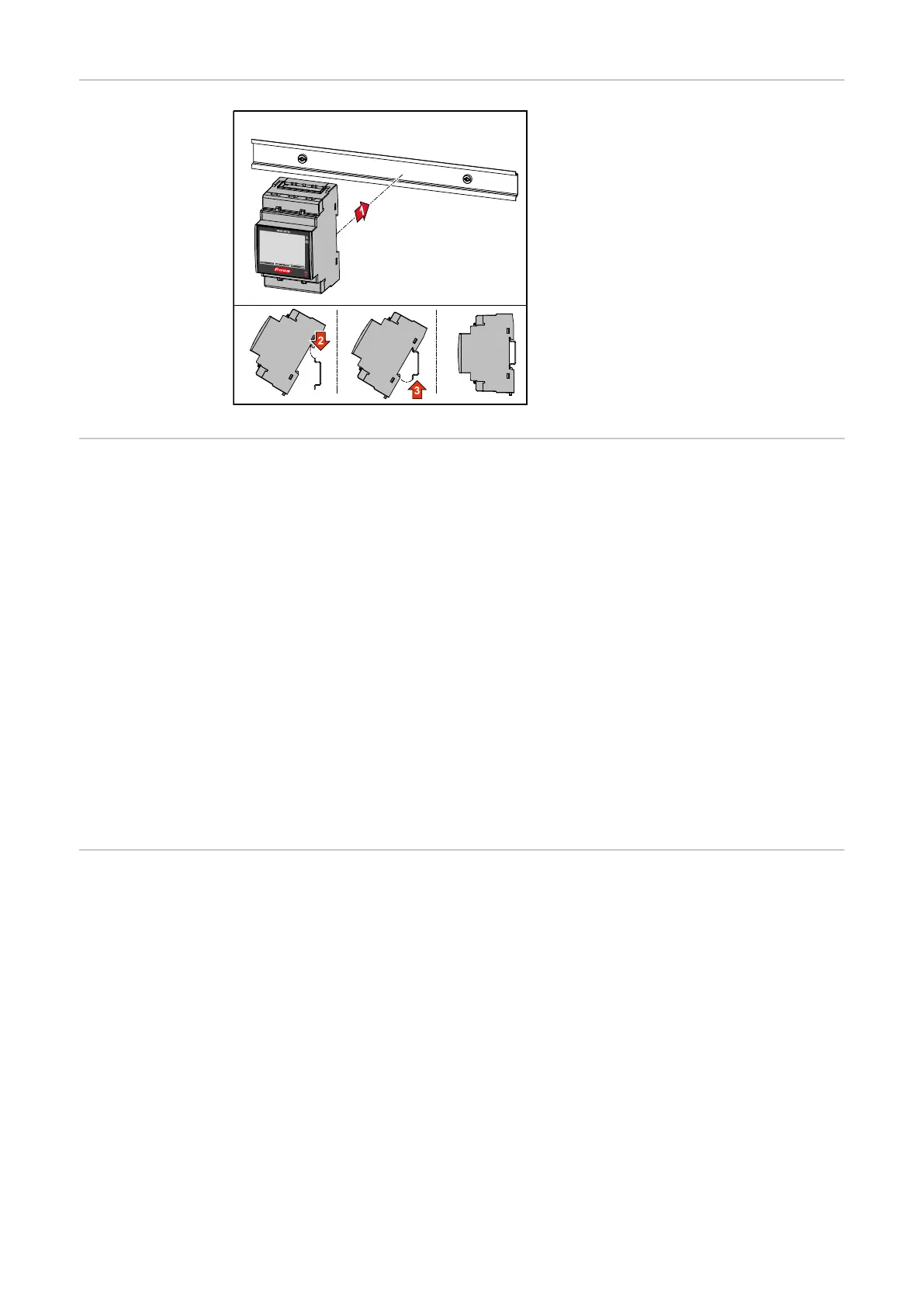
Installation The Fronius Smart Meter TS can be
mounted on a 35 mm DIN rail. The
housing comprises 3 modules accord-
ing to DIN 43880.
Protective cir-
cuit
The Fronius Smart Meter TS is a hard-wired device and requires a disconnecting
device (circuit breaker, switch or disconnector) and overcurrent‑protection (auto-
matic‑circuit breaker).
The Fronius Smart Meter TS consumes 10 - 30 mA, the nominal capacity of the
disconnecting devices and the overcurrent‑protection is determined by the wire
thickness, the mains voltage and the required breaking capacity.
-
Disconnecting devices must be mounted within sight and as close as possible
to the Fronius Smart Meter TS; they must also be easy to use.
-
The disconnecting devices must satisfy the requirements of IEC 60947-1
and IEC 60947-3, as well as all national and local regulations for electrical
systems.
-
To monitor more than one mains voltage, use connected‑automatic circuit
breakers.
-
The overcurrent‑protection must protect the mains terminals with the desig-
nations L1, L2 and L3. In rare cases, the neutral conductor has an overcur-
rent‑protection, which must interrupt both neutral and non-earthed cables
concurrently.
Auxiliary power
supply cabling
IMPORTANT!
An auxiliary power supply is required to operate the Fronius Smart Meter TS. The
fuse (F) must comply with the national standards and guidelines as well as the
dimensions of the conductors.
18