2-5
2-3 Names and Functions
Functions
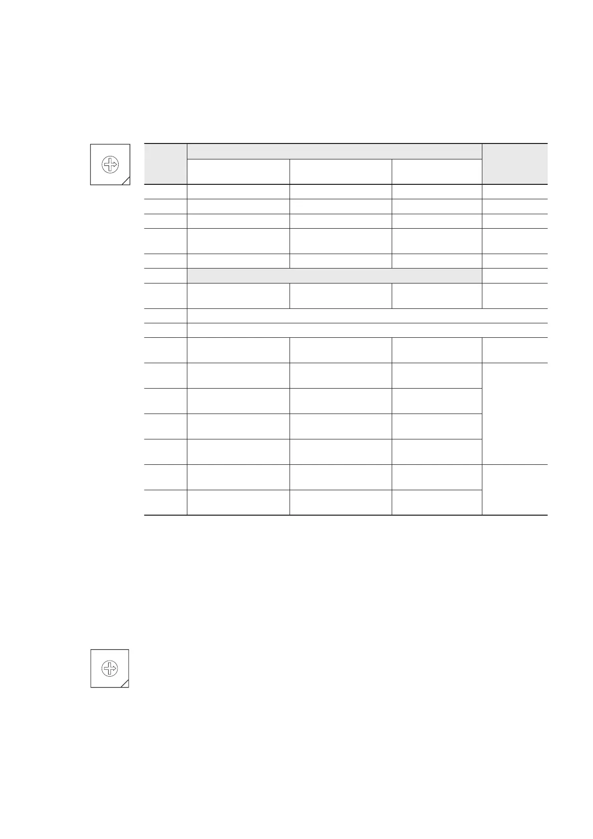
2) Mode selection switch
This switch is used to select a connectable device, the signal conversion and the self-diagnosis for the RS-232C port and
the RS-485 port.
MODE
C
D
E
F
0
1
B
A
9
8
7
6
5
4
3
2
Switch
No.
Mode
Remarks
RS-232C port RS-485 port
RS-232C <=> RS-485
Signal conversion
0 General purpose device General purpose device Not available
1 Programming loader General purpose device Not available
2 General purpose device Programming loader Not available
3 Programming loader Programming loader Not available
Applies to
V2535 or later.
4 General purpose device General purpose device Available
5
Not used
6
Modem-loder
19200 bps
General purpose device Not available
Applies to
V1031 or later.
7 Self-diagnosis mode 1 (diagnoses internal memory and LED)
8 Self-diagnosis mode 2 (diagnoses RS-232C, RS-485 turning back)
9
Modem-loder
19200 bps
Programming loader Not available
Applies to
V1031 or later.
A
Modem-loder
9600 bps
General purpose device Not available
Applies to
V2535 or later.
B
Modem-loder
9600 bps
Programming loader Not available
C
Modem-loder
38400 bps
General purpose device Not available
D
Modem-loder
38400 bps
Programming loader Not available
E
Modem-loder
76800 bps
General purpose device Not available
Applies to
V2536 or later.
(Note 5)
F
Modem-loder
115200 bps
Modem-loder
115200 bps
—
Note 1: For details of the function mode, refer to “3-2 System configuration.”
Note 2: For the self-diagnosis, refer to “3-4 Self-diagnosis.”
Note 3: “Programming loader” is the mode for connecting to D300win. Communication specifications are fixed to” 38400
bps” for transmission speed, “8 bits” for data length, “1 bit” for stop bits, and “even” for parity.
Note 4: “Modem-loader" is the mode that is basically used to connect to D300win loader via a modem. In general, for
modems, “none” is specified for parity. Therefore, in this mode, communication specifications become “8 bits” for
data length, “1 bit” for stop bits, and “none” for parity.
Note 5: Either channel is selected and used.
3) RS-485 station No. selection switch
This switch used to select a RS-485 station number of NP1L-RS1 or NP1L-RS4. Selecting range is 0 to F.
C
D
E
F
0
1
B
A
9
8
7
6
5
4
3
2
RS485
No.
(0-F)
 Loading...

