App.4-5
Appendix 4 Additional Explanation
for NP1L-RS5
Appendix 4-7 Detailed RAS
(Related page: p7-3)
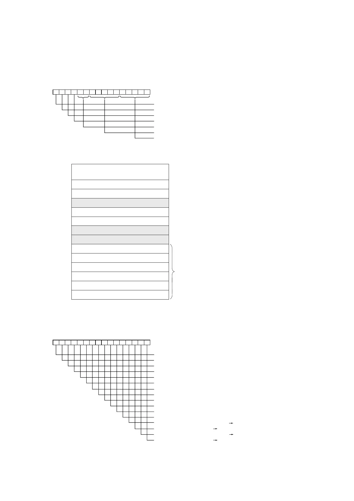
RS-485 station No. switch setting appears on bit 5 to 9, 0 to 4 on communication status area.
9876543210FEDCBA
Mode switch (x 8)
Mode switch (x 4)
Mode switch (x 2)
Mode switch (x 1)
Reserved
CH1 station number
CH2 station number
No. 4 and No. 5 information newly added to detailed RAS information.
(Almost same as RS3 specification)
0
Status of general purpose
communication module
1
Status of CH1
2 Status of CH2
3
Not used
4
Self-diagnostic 1
5
Self-diagnostic 2
6
Not used
7
Not used
8 Number of parity error occurrences
9
Number of framing error occurrences
10
Number of overrun error occurrences
11
Send buffer overflow
12 Receive buffer overflow
13 Loopback buffer overflow
No.4 (Self-diagnostic 1)
Bit 0: External RAM abnormal
Bit 1 to 15: Not used
No.5 (Self-diagnostic 2)
15
14
13 12 11 10 9 8 7 6 5 4 3
2
10
Not used
Not used
Not usedl
Not used
Not used
Not used
Not used
Not used
Not used
Not used
Not used
Not used
CH1 Send/Receive data abnormal (SD RD) (Send data error detected)
CH1 Loop back abnormal (SD RD) (Communication error detected)
CH2 Send/Receive data abnormal (SD RD) (Send data error detected)
CH2 Loop back abnormal (SD RD) (Communication error detected)
RS-232C
 Loading...

