App.4-3
Appendix 4 Additional Explanation
for NP1L-RS5
3) RS-485 station No. switch
Used to set RS-485 station No. for CH1, CH2 individually.
Range: 00 to 1F (HEX)
ON 1 2
MSB
CH1
CH1
No.
CH2
No.
CH2
c
D
E
F
0
1
B
A
9
8
7
6
5
3
2
c
D
E
F
0
1
B
A
9
8
7
6
5
4
3
2
The second digit is set by dip switch.
OFF: 0
ON: 1
The first digit is set by rotary switch. (0 to F)
4) Terminating resistor ON/OFF switch
This switch used to select the ON/OFF of the RS-485 terminating resistor. There are three positions for this switch.
noitisophctiwS sutatS
thgiR.elbaliavasirotsisergnitanimret,epyteriw-2
retneC.elbaliavatonsirotsisergnitanimreT
tfeL.elbaliavasirotsisergnitanimret,epyteriw-4
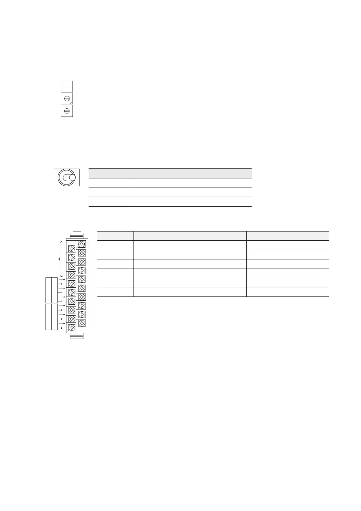
5) RS-485 terminal block
It is used to connect RS-485 cable (20 poles, M3 screw).
SDB
SDA
RDA
RDB
FG
SG
CH1
CH2
SDA
SDB
RDB
RDA
SG
FG
Unused
emanlangiS noitceridlangiS5SR>==<ecivedlanretxE noitpircseD
ADS>==ataddneS)+(enillangis
BDS>==ataddneS)-(enillangis
ADR==<atadevieceR)+(enillangis
BDR==<atadevieceR)-(enillangis
GS )nruternommoC(dnuorglangiS
GFdnuorgemarF
For wiring, please refer “6-2 Wiring Method”.
However, in case of 2-wire, short SDA and RDA (+), SDB and RDB (-) and connect to other device.
In case of RS5, no need to connect zener diode as it is already included in module.
 Loading...

