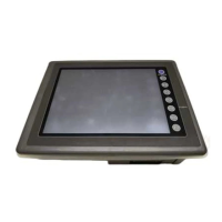
Do you have a question about the Fuji Electric UGx20 SERIES and is the answer not in the manual?
| Brand | Fuji Electric |
|---|---|
| Model | UGx20 SERIES |
| Category | Touch Panel |
| Language | English |
Lists available UG series manuals for operation, function, and communication.
Critical safety instructions for hazardous situations, injury prevention, and property damage.
Best practices for operating, maintaining, and disposing of the POD unit safely.
Lists the history of revisions made to the manual.
Key features, usage, environmental limits, and location recommendations for POD operation.
Illustrates system configurations, lists models, and describes peripheral equipment and options.
Identifies front/rear components and provides physical dimensions for various UG models.
Details the process of cutting the mounting panel and inserting fixtures for UGx20 units.
Explains power connection, grounding, and cable routing for noise prevention.
Details serial connectors, modular jacks, and wiring for various communication protocols.
Lists and describes connection procedures for representative PLC types and communication interfaces.
Lists general specs, display types, resolutions, interface details, and performance limits.
Details how to set dip switches for memory extension, terminal resistance, and communication settings.
Shows pin arrangement and explains setting MJ1/MJ2 via software (UG00S-CW).
Describes connecting a bar code reader to POD via modular jack MJ1/MJ2 using UG00C-B cable.
Explains connecting a printer via connector CN2 for hard-copying screen displays or data.
Describes connecting video or CCD cameras to UGx20 for displaying images.
Explains connecting a personal computer via CN3 for displaying PC screen images on UG420H-TC.
Allows manipulating Windows screens on POD using touch switches instead of a mouse.
Describes the Main Menu, I/O tests, self-loop tests, and switch checks for diagnostics.
Describes transferring screen data between POD and a memory card.
Describes the connection procedure for the UG00P-U1 and UG00P-U2 I/O units.
Details connecting memory card recorders and extension units, including battery precautions.
Guides on installing optional communication I/F units like UG03I-x and UG02I-x.
Explains UG00P-DI installation, usage for debugging, and transfer utility.
Step-by-step guides for replacing backlight units on various UG models.
Explains the ladder transfer function for debugging and monitoring PLC memory.
Covers POD-PLC connection diagrams, communication settings, and software usage.