En-9
CAUTION
The primary power supply capacity is for the air conditioner itself, and does not •
include the concurrent use of other devices.
Do not use crossover power supply wiring for the outdoor unit.•
If the electrical power is inadequate, contact your electric power company.•
Install a breaker in a location that is not exposed to high temperatures. •
If the temperature surrounding the breaker is too high, the amperage at which the
breaker cuts out may decrease.
Use a breaker that is capable of handling high frequencies. Because the outdoor •
unit is inverter controlled, a high-frequency breaker is necessary to prevent a
malfunction of the breaker itself.
When the electrical switchboard is installed outdoors, place it under lock and key •
so that it is not easily accessible.
Do not fasten the power supply cable and connection cable together.•
Always keep to the maximum length of the connection cable. Exceeding the •
maximum length may lead to erroneous operation.
The static electricity that is charged to the human body can damage the control •
PC Board when handling the control PC Board for address setting, etc.
Please keep caution to the following points.
Provide the grounding of Indoor unit, Outdoor unit and Option equipment.
Cut off the power supply (breaker).
Touch the metal section (such as the unpainted control box section) of the indoor
or outdoor unit for more than 10 seconds. Discharge the static electricity in your
body.
Never touch the component terminal or pattern on the PC Board.
Knockout hole6. 2.
CAUTION
Be careful not to deform or scratch the panel while opening the knockout holes.•
When cables are routed from the unit, a protection sleeve for the conduits can •
be inserted at the knockout hole.
When cables through the opened knockout hole, install the one-touch bush. •
For the installation method of the one-touch bush, refer to "6.6. Connecting of
wiring".
It is recommended to apply anti-rust paint to the edge of the knockout hole.•
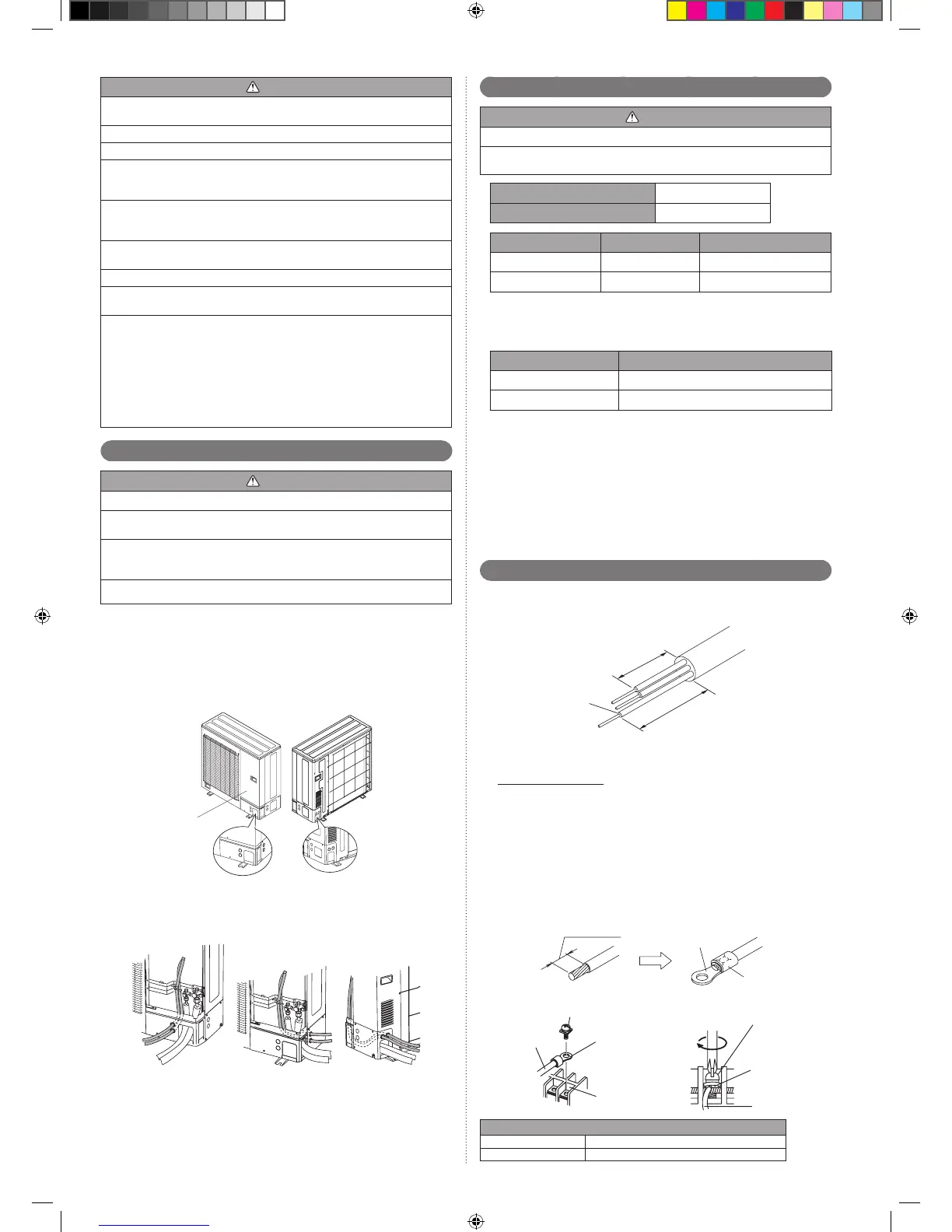
Knockout holes are provided for wiring. (Fig. A)•
Knockout holes are provided 2 each in the same size in front, lateral and rear •
sides. (Fig. B)
Fig. A
Service panel
Fig. B
Front connection Lateral connection Rear connection
Electrical requirement6. 3.
CAUTION
Be sure to install a breaker of the specied capacity.
Regulation of cables and breaker differs from each locality, refer in accordance with
local rules.
Voltage rating 1Φ 230V (50Hz)
Operating range 198-264V
Cable Cable size (mm
2
) *1) Remarks
Power supply cable 6.0 2 cable + Ground, 1 Ø 230V
Connection cable 2.5 3 cable + Ground, 1 Ø 230V
Selected sample: Select the correct cable type and size according to the country 1)
or region’s regulations.
Max. wire length: Set a length so that the voltage drop is less than 2%. Increase
the wire diameter when the wire length is long.
Breaker Specication *2)
Circuit breaker (over current) Current : 32 (A)
Earth leakage breaker Leakage current : 30mA 0.1sec or less *3)
Select the appropriate breaker of the described specication according to the 2)
national or regional standards.
Select the breaker that enough load current can pass through it. 3)
Use conformed cable with Type60245 IEC57.•
Before starting work check that power is not being supplied to all poles of the •
indoor unit and outdoor unit.
Install all electrical works in accordance to standard.•
Install the disconnect device with a contact gap of at least 3mm in all poles nearby •
the units. (Both indoor unit and outdoor unit)
Wiring size must comply with the applicable local and national code.•
Unit wiring6. 4.
When stripping off the coating of a lead wire, always use a special tool such as a •
wire stripper. If there is no special tool available, carefully strip the coating with a
knife etc.
Earth cable
30mm
35mm
Power supply cable
How to connect wiring to the terminal
Caution when wiring cable
(1) Use crimp-type terminals with insulating sleeves as shown in the gure to
connect to the terminal block.
(2) Securely clamp the crimp-type terminals to the wires using an appropriate tool
so that the wires do not come loose.
(3) Use the specied wires, connect them securely, and fasten them so that there
is no stress placed on the terminals.
(4) Use an appropriate screwdriver to tighten the terminal screws. Do not use a
screwdriver that is too small, otherwise, the screw heads may be damaged
and prevent the screws from being properly tightened.
(5) Do not tighten the terminal screws too much, otherwise, the screws may break.
(6) See the table below for the terminal screw tightening torques.
Sleeve
Strip : 10mm
Crimp-type
terminal
Wire
Screw with special washer
Crimp-type terminal
Terminal blocks
Screw with
special washer
Wire
Crimp-type
terminal
Tightening torque [N·m (kgf·cm)]
M4 screw 1.2 to 1.8 (12 to 18)
M5 screw 2.0 to 3.0 (20 to 30)
 Loading...