Refrigerant recovery method7. 4.
※
Please perform the refrigerant recovery according to the local law and rules.
The refrigerant recovery of this type of equipment must be performed by a refrigerant
recovery machine.
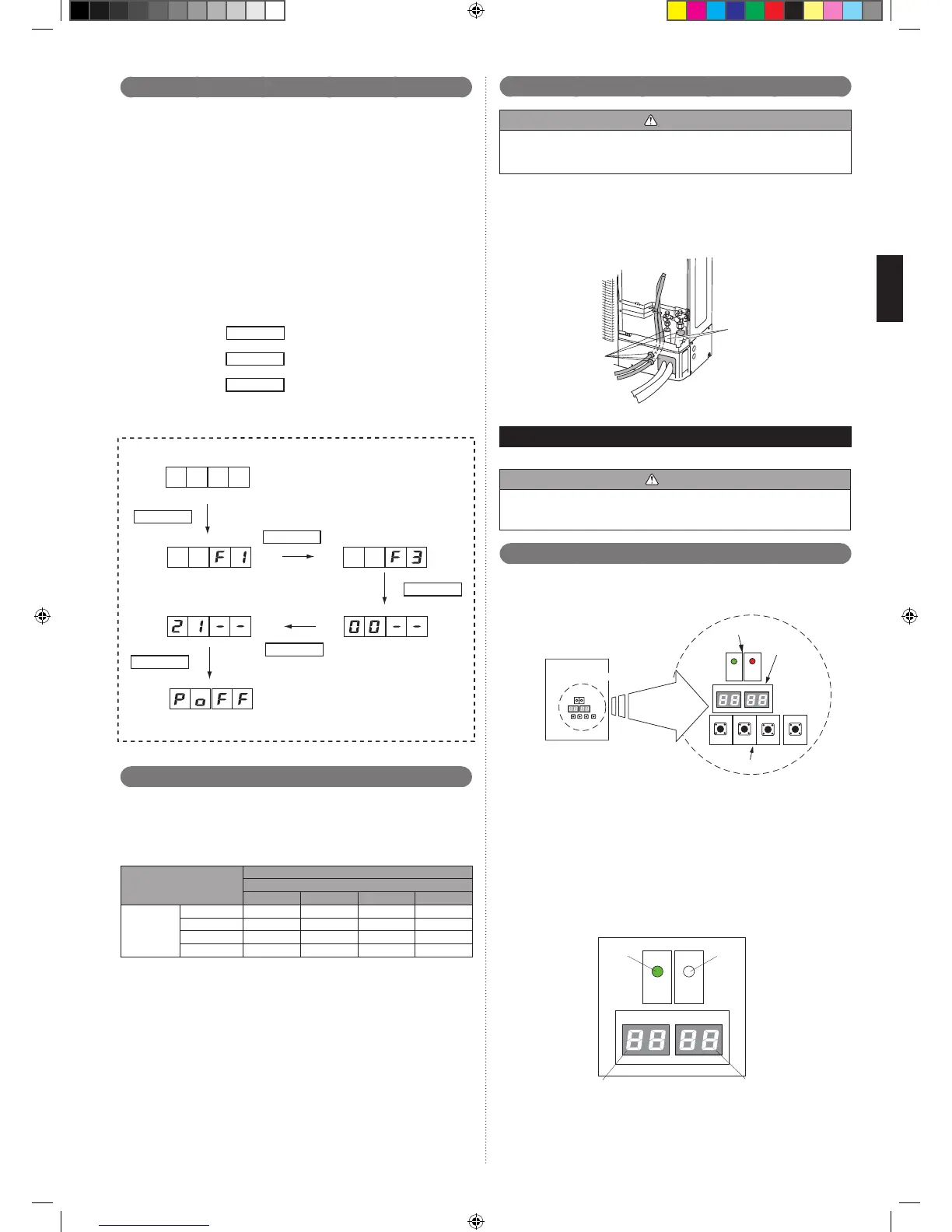
Turn on both the power supplies of the outdoor unit and the branch boxes.
①
Press the “MODE/EXIT” button of the outdoor unit when all units are in stop
②
operation state.
Match the 7 seg. display to “F3” by pushing the SELECT button.
③
Press the “ENTER” button.
④
Match the 7 seg. display to “21” by pushing the “SELECT” button.
⑤
Press the “ENTER” button for about 5 seconds.
⑥
Turn off the power supplies of all units when “P.oFF” is displayed.
⑦
Perform the refrigerant recovery with the refrigerant recovery machine.
⑧
It cannot be operated in the “P.oFF” state. Please turn on the power supplies of all
units again in case of performing operation.
MODE/EXIT
: Press the “MODE/EXIT” button.
: Press the “SELECT” button.
: Press the “ENTER” button.
SELECT
ENTER
MODE/EXIT
SELECT ×2
×3
SELECT
ENTER
ENTER
(Blinking) (Blinking)
(Blinking)
(Blinking)
7 seg.display
Installing insulation7. 5.
Use an insulation on the refrigerant pipes to prevent condensation and dripping.•
Determine the thickness of the insulation material by referring to Table A.•
Table A, Selection of insulation
(for using an insulation material with equal heat transmission rate or below
0.040 W/(m·k))
Relative humidity
[mm (in.)]
Insulation material
Minimum thickness [mm]
70% or more 75% or more 80% or more 85% or more
Pipe diameter
6.35 (1/4) 8 10 13 17
9.52 (3/8) 9 11 14 18
12.70 (1/2) 10 12 15 19
15.88 (5/8) 10 12 16 20
If the ambient temperature and relative humidity exceed 32 °C, increase the level •
of heat insulation for the refrigerant pipes.
Filling with putty7. 6.
WARNING
Fill the piping holes and wiring holes with putty (supplied locally) to avoid any gap •
(Fig A). If small animals such as insects enter the external unit, a short circuit may
be caused near electrical components in the service panel.
If the outdoor unit is installed at a level that is higher than the indoor unit, the water •
that has condensed in the 3-way valve of the outdoor unit could travel to the indoor
unit. Therefore, use putty in the space between the pipe and the insulation to
prevent the entry of water to the indoor units.
Fig. A
Putty
Insulation
FIELD SETTING8.
CAUTION
Discharge the static electricity from your body before setting up the DIP switches.
Never touch the terminals or the patterns on the parts that are mounted on the
board.
Field setting switches8. 1.
Set the functions of an outdoor unit with the push buttons (SW931, SW932 and
SW933) while observing the 7 seg. display (LED961 and LED962) on the printed
circuit board.
Outdoor unit printed circuit board
Push button
LED lamp
7 seg.display
PREPARATION
1
Be sure to check that the operation of the outdoor unit has stopped (be sure to stop
the operation if it is still running), and turn off the power.
2
Remove the front panel of the outdoor unit, and remove the lid of the electrical
component box in order to expose the printed circuit board.
3
Turn on the power of the outdoor unit.
As shown in the above gure, make sure that the POWER/MODE indicator lamp
(LED981) is on and the ERROR indicator lamp (LED982) is off.
If the ERROR indicator lamp (LED982) ashes, it indicates that an error has •
occurred. Check wiring and power supply. After making sure that the ERROR
indicator lamp (LED982) has turned off, proceed to the next step.
 Loading...