Check if [L] is ared uniformly
and is not cracked or scratched.
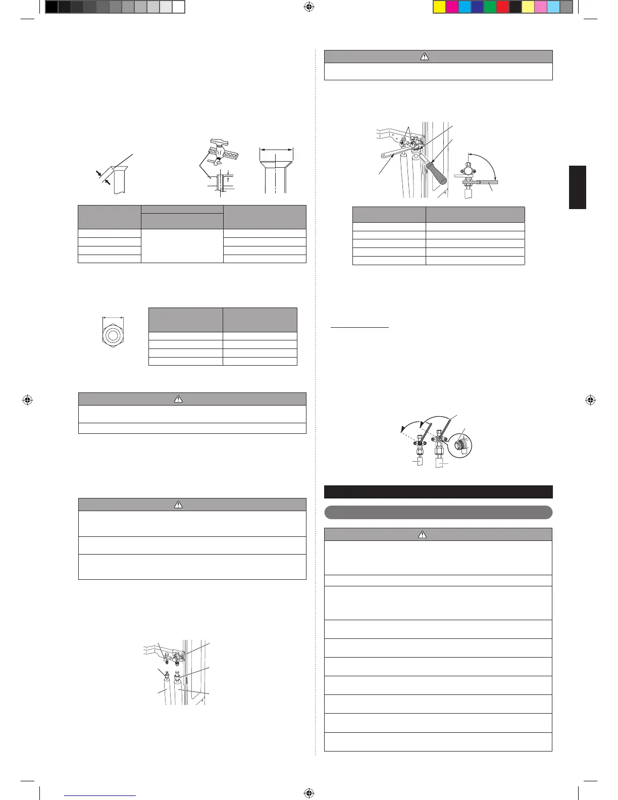
Pipe
A
B
Die
Pipe outside
diameter [mm (in.)]
Dimension A (mm)
Dimension B
0
- 0.4
[mm]
Flare tool for R410A,
clutch type
6.35 (1/4)
0 to 0.5
9.1
9.52 (3/8) 13.2
12.70 (1/2) 16.6
15.88 (5/8) 19.7
When using conventional are tools to are R410A pipes, the dimension A should •
be approximately 0.5mm more than indicated in the table (for aring with R410A
are tools) to achieve the specied aring. Use a thickness gauge to measure the
dimension A.
Pipe outside
diameter
[mm (in.)]
Width across ats
of Flare nut
[mm]
6.35 (1/4) 17
9.52 (3/8) 22
12.70 (1/2) 26
15.88 (5/8) 29
Width across ats
Bending pipes5. 3. 2.
CAUTION
To prevent breaking of the pipe, avoid sharp bends. Bend the pipe with a radius of •
curvature of 100mm or more.
If the pipe is bent repeatedly at the same place, it will break.•
If pipes are shaped by hand, be careful not to collapse them.•
Do not bend the pipes at an angle of more than 90°.•
When pipes are repeatedly bent or stretched, the material will harden, making it •
difcult to bend or stretch them any more.
Do not bend or stretch the pipes more than 3 times.•
Pipe connection5. 3. 3.
CAUTION
Be sure to install the pipe against the port on the indoor unit and the outdoor unit •
correctly. If the centering is improper, the are nut cannot be tightened smoothly.
If the are nut is forced to turn, the threads will be damaged.
Do not remove the are nut from the outdoor unit pipe until immediately before •
connecting the connection pipe.
After installing the piping, make sure that the connection pipes do not touch the •
compressor or outer panel. If the pipes touch the compressor or outer panel, they
will vibrate and produce noise.
(1) Detach the caps and plugs from the pipes.
(2) Center the pipe against the port on the outdoor unit, and then turn the are nut
by hand.
(3) Tighten the are nut of the connection pipe at the outdoor unit valve connector.
(4) After tightening the are nut by hand, use a torque wrench to fully tighten it.
3-way valve (Liquid)
3-way valve (Gas)
Connection pipe
(Liquid)
Flare nut
Connection pipe
(Gas)
Flare nut
CAUTION
Hold the torque wrench at its grip, keeping it in a right angle with the pipe, in order •
to tighten the are nut correctly.
Outer panel may be distorted if fastened only with a wrench. Be sure to x the •
elementary part with a holding wrench (spanner) and fasten with a torque wrench
(refer to below diagram). Do not apply force to the blank cap of the valve or hang a
wrench, etc., on the cap. If blank cap is broken, it may cause leakage of refrig
erant.
Blank cap
Flare nut
90°
Torque wrench
Holding
wrench
Torque wrench
Flare nut
[mm (in.)]
Tightening torque
[N·m (lgf·cm)]
6.35 (1/4) dia. 16 to 18 (160 to 180)
9.52 (3/8) dia. 32 to 42 (320 to 420)
12.70 (1/2) dia. 49 to 61 (490 to 610)
15.88 (5/8) dia. 63 to 75 (630 to 750)
19.05 (3/4) dia. 90 to 110 (900 to 1100)
Handling precautions for the valves5. 3. 4.
Mounted part of Blank cap is sealed for protection.•
Fasten blank cap tightly after opening valves.•
Operating the valves
Use a hexagon wrench (size 4mm).•
Opening (1) Insert the hexagon wrench into the valve shaft, and turn it •
counterclockwise.
(2) Stop turning when the valve shaft can no longer be turned.
(Open position)
Closing (1) Insert the hexagon wrench into the valve shaft, and turn it •
clockwise.
(2) Stop turning when the valve shaft can no longer be turned.
(Closed position)
Opening direction
Hexagon wrench
Seal (blank cap
installation portion)
Liquid pipe
Gas pipe
Opening direction
ELECTRICAL WIRING6.
The precautions of electrical wiring6. 1.
WARNING
Wiring connections must be performed by a qualied person in accordance with •
specications.
The rated supply of this product is 50Hz, 230V. Use a voltage within the range of
198-264V.
Before connecting the wires, make sure the power supply is OFF.•
Be sure to install a breaker of the specied capacity. When selecting breaker, •
please comply with the laws and the regulations of each country. One breaker
must be installed on the power supply of the outdoor unit. Wrong selection and
setup of the breaker will cause electric shock or re.
Be sure to install an earth leakage breaker. Otherwise, it will cause electric shock •
or re.
Do not connect AC power supply to the transmission line terminal board. •
Improper wiring can damage the entire system.
Connect the connector cord securely to the terminal. •
Faulty installation can cause a re.
Make sure to secure the insulation portion of the connector cable with the cord •
clamp. A damaged insulation can cause a short circuit.
Never install a power factor improvement condenser. Instead of improving the •
power factor, the condenser may overheat.
Before servicing the unit, turn the power supply switch OFF. Then, do not touch •
electric parts for 10 minutes due to the risk of electric shock.
Make sure to perform grounding work. Improper grounding work can cause •
electric shocks.
 Loading...