Questions? Call (315) 298-5121, or visit us online at www.fulton.com
SECTION 2 CAL-IOM-2012-1220 INSTALLATION
2-5
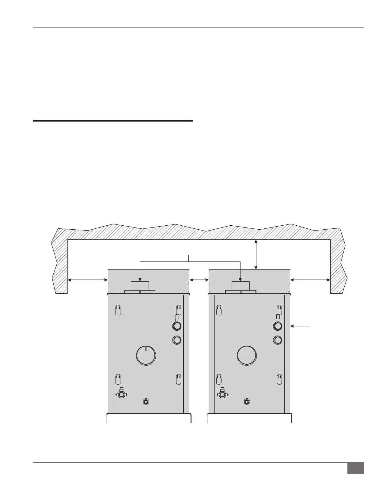
2. Appropriate front, back, side and top clearances
must be maintained (Figure 1). This will allow access
around the equipment to facilitate maintenance and
a safe work environment. A four inch (101.6 mm) side
clearance is acceptable between boilers.
3. Ensure all labels on the boiler will be fully visible for
maintenance and inspection.
Install Boiler Trim
Each Caliber boiler is supplied with a safety relief valve sized
in accordance with ASME requirements. The safety relief valve
comes pre-piped into the water outlet manifold.
Adhere to the following installation requirements:
1. The safety relief valve (Figure 1) must:
» Be connected to the coupling located in the
top rear outlet section of the boiler.
» Be installed in the vertical position.
» Be installed with a 4 inch (101.6 mm) nipple
between the boiler and the safety valve.
NOTE: ´ Safety relief valve size is determined by trim pressure
and is supplied in the trim kit along with appropriate bushing,
inlet and outlet sizes.
The discharge of the safety relief valve is piped to the back
of the boiler. The installer must complete the piping to a safe
location. The discharge pipe must:
» Not have a diameter less than the full area of the
valve outlet.
» Be as short and straight as possible and so
arranged as to avoid undue stress on the valve.
» Be supported by means other than the safety
valve itself.
» Be piped to avoid danger of scalding personnel.
NOTE: ´ Each boiler is equipped with a pressure-temperature
gauge to be installed in the outlet piping section of the boiler.
FIGURE 1 CALIBER HYDRONIC BOILER CLEARANCES
36”
36”
SAFETY
RELIEF
VALVE
4”
AIR INLET
36”