© The Fulton Companies 2012
INSTALLATION CAL-IOM-2012-1220 SECTION 2
2-20
! WARNING
The exhaust vent installer should be
familiar with Federal Codes as well
as local codes and regulations.
Fulton cannot assume responsibility
for an air intake or exhaust
arrangement where Caliber boilers
are common vented with any other
type of equipment.
4 CAUTION
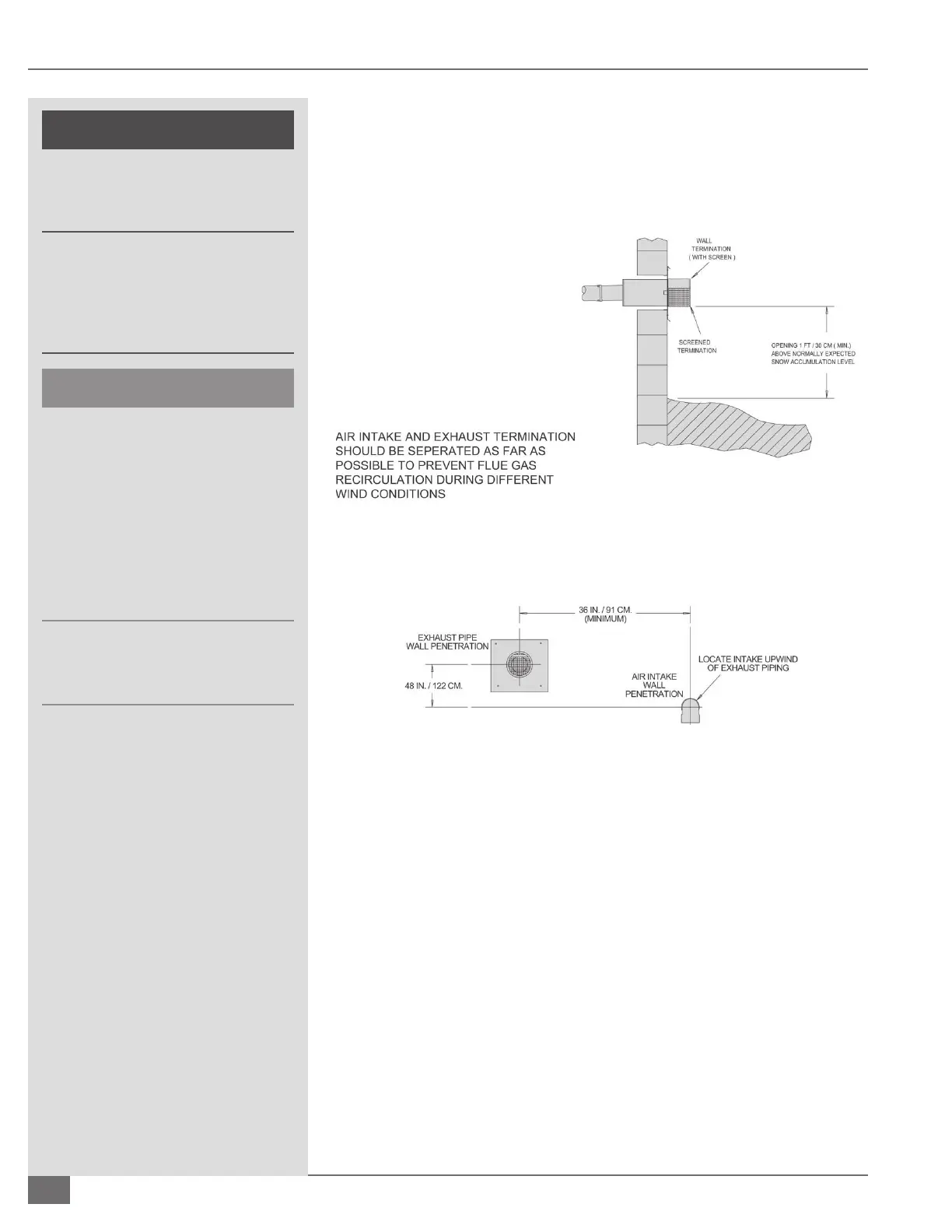
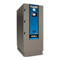
To prevent the possible re-circulation
of ue gases, the vent designer must
take into consideration such things
as prevailing winds, eddy zones,
building con gurations, etc. It is the
responsibility of the installer to locate
the exhaust duct in such a way that it
does not become blocked due to snow,
ice, and other natural or man-made
obstructions.
Do not locate the vent termination too
close to shrubbery as ue products may
stunt their growth or kill them.
system may be installed is 3.25 inches (82.5 mm). Maximum wall thickness
through which vent system may be installed is 20 inches (508 mm).
FIGURE 7 VENTING TERMINATIONS
¡ Wall Thimble Installation
Adhere to the following for installation (see Figure 8):
1. The thimble is inserted through the wall from the outside. Secure the
outside ange to the wall with nails or screws, and seal with adhesive
material.
2. Install the inside ange to the inside wall, secure with nails or screws, and
seal with adhesive material.
3. Pass the vent pipe through the thimble from the outside and join to the
rest of the vent system.
4. Seal the pipe to the thimble ange with adhesive material.
5. Install two pipe retaining clamps around the intake as well as vent pipes