16
VMP IOM
a. Make sure two check valves are
installed between the boiler and pump
(one check valve is supplied with the
unit).
b. In a closed system an end of the line
trap should be installed.
c. There are four blow-down valves on the
boiler: Two main bottom blow-down
valves, the gauge glass blow-down
valve, and the water column blow-down
valve. All blow-down connections must
be piped to blow-down seperator.
All these procedures should be done in
accordance with state and/or local codes.
The water column blow-down valve and the
gauge glass blow-down valve should be
connected to the main blow-down line.
Steam Supply
Pipe the steam supply line from the top right
side of the boiler.
Steam Safety Valve
1. Before installing, be sure that all pipes
and connections have been blown
clean. Pipe compound or dope is used
on external threads only. Be sure inlet of
valve is free of any foreign material.
2. Do not use a pipe wrench! When
making installation, use proper type and
size wrench.
3. The valve should be installed in a
vertical upright position in the
connection provided on the top left side
of the boiler with no unnecessary
intervening pipe. Under no
circumstances should there be a shut off
valve or restriction of any kind between
the safety valve and the connection
provided.
4. Do not cap or plug drain hole in the side
of valve body.
5. Since the purpose of this safety valve is
to protect against an overpressure
situation, it will loudly discharge hot
steam in doing so. Therefore, it is
recommended that a discharge pipe be
securely installed and run to a safe point
of disposal.
6. When a discharge pipe is used, it must
be of a pipe size equal to or greater than
that of the valve outlet. Use schedule 40
discharge pipe only. Do not use
schedule 80, extra strong or double
extra strong discharge pipe or
connections. It must be as short and
straight as possible and so arranged as
to avoid undue stress on the valve. It
must have an ample provision for
draining condensate at or near the valve
outlet. It must terminate freely to
atmosphere with no intervening valve of
any description and it must be securely
anchored and supported.
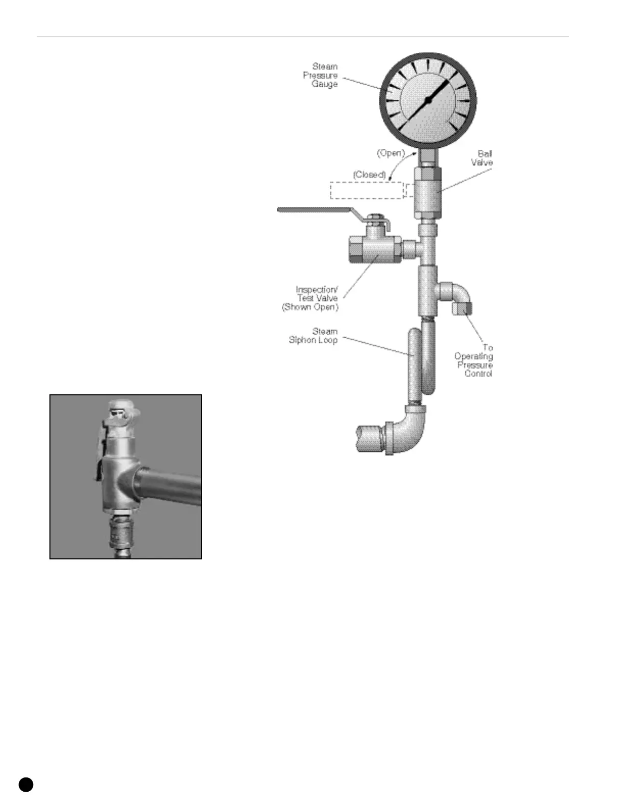
Steam Pressure Gauge
Assembly
The gauge should be facing front towards
the panel box and/or operator of the boiler.
Except as noted, each assembly or any of
its component parts may be oriented, other
than as shown to provide improved
operating clearances and/or view of gauge.
Before installing steam gauge on the
siphon, add a small amount of water to the
siphon to create a water seal to buffer the
gauge element. This must be done to
prevent inaccurate pressure readings and
/or premature failure of the gauge. Install
the steam gauge into the siphon on the
water column.
Installation