VMP IOM
21
Electrical Requirements
1. Connect wiring as shown in the wiring
diagram which is furnished inside the
electrical control panel box.
2. Be sure to install a separate disconnect
for each piece of equipment. The
disconnects should be installed in
compliance with the NEC (National
Electric Code) and all local codes.
3. Connections for an optional audible
alarm are provided in the control panel
and are clearly indicated on the diagram.
Fresh Air Supply
for Boiler
It is most important to provide free access of
air to the boiler. To burn fuel properly, it
requires one square inch opening of fresh air
for every 3,000 BTU input of fuel. (6.4cm
2
for
every 756 Kcal).
Proper ventilation of the boiler room is
essential for good combustion. Install two
fresh air openings, one at a low level 24”
(610 mm) from floor and one at a higher
level in the boiler room wall.This will provide
a flow of air to exhaust the hot air from the
boiler room. Boiler room temp not to
exceed 100°F.
The following openings are recommended for
each size boiler:
Make Up Air Openings
BHP FT
2
M
2
40 5 .46
50 5 .46
60 7.5 .69
80 12.5 1.11
100 16 1.49
130 21 1.95
150 24 2.23
Be sure total BHP = proper make up air
opening size.
These measurements are subject to state
and local regulations. The installation of
exhaust fans in a boiler room is not
recommended.
An exhaust fan, or similar equipment can
create down draft in the stack or restrict the
burner’s air supply which will result In poor
combustion. It is essential that only fresh air
is allowed to enter the combustion air
system. Foreign substances, such as
combustible volatiles and lint, in the
combustion system can create hazardous
conditions.
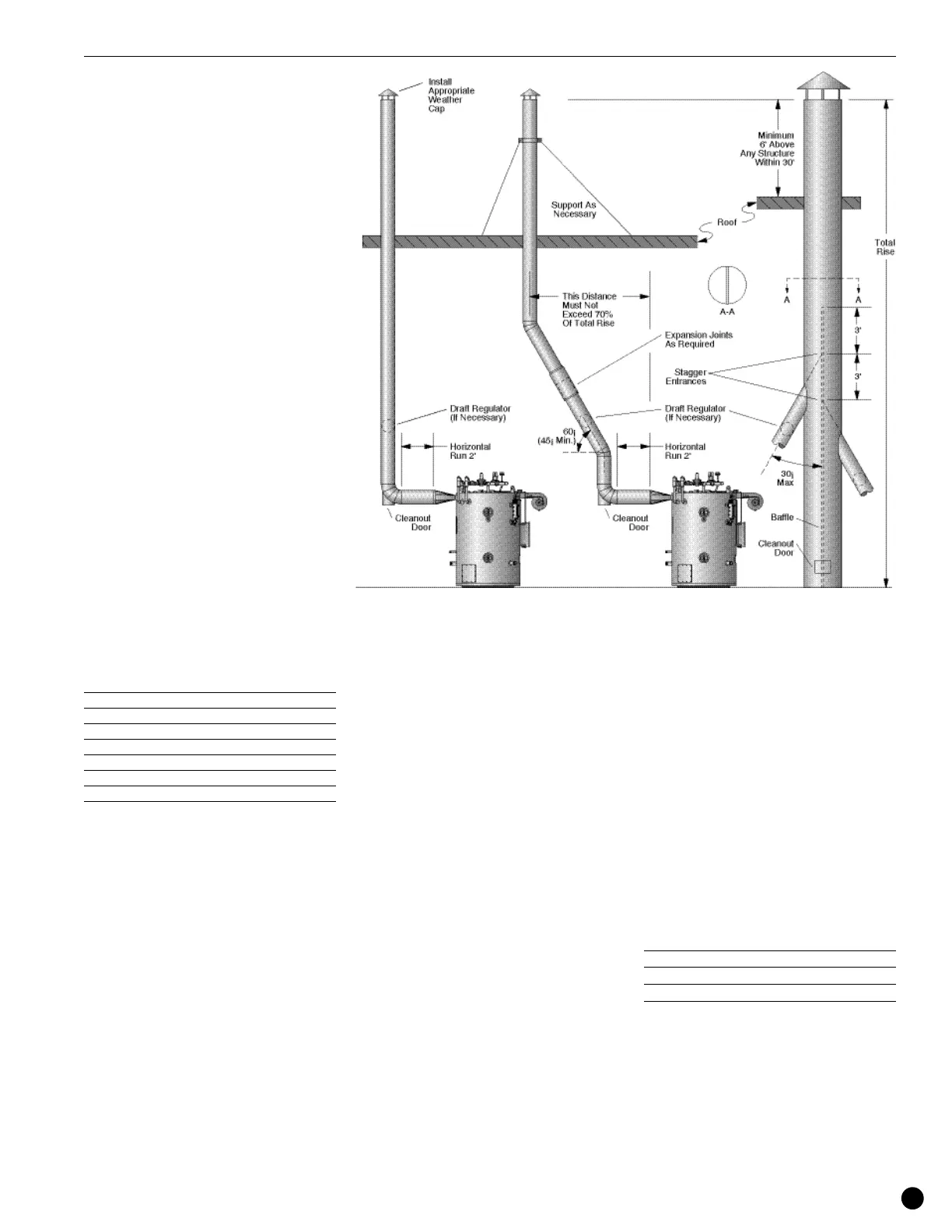
Conventional Venting
The stack should rise continuously to the
connection with the chimney, and should
contain no more than two bends at 45°
angles or less. If required as the result of
space limitations, one 90° elbow can be
fitted at the back of the boiler. There should
be two feet of straight, horizontal flue before
any bends or turns. Any alternative stack
arrangement must supply a negative .02 -
.04” W.C. pressure (0.508 to 1.016 mm)
with the burner off.
The run in the total distance of stack ducting,
as measured in a straight line from the outlet
of the boiler to the outlet of the stack, should
not exceed 70% of the rise. With the
exception of a duct run described in Item a,
horizontal sections of ducting must be
avoided, and should not exceed four feet of
total run.
The stack and chimney must be
constructed from material that is rated for
1000°F operating temperature. Check all
local codes for exact requirements.
Adequate provision must be made for the
support of the weight of the chimney and
stack to avoid having too great a load
imparted to the flue outlet connection of the
boiler.
The proper flue size and draft control is
most important for proper burner operation.
The flue must be
as large or larger than the outlet on the
boiler. Avoid flue piping and elbows by
placing the boiler as close as possible to the
chimney.
A mechanical draft regulator should be
installed in the flue outlet. Do not install the
draft regu-lator prior to the first turn of the
flue.
BHP Boiler Flue Size
IN MM
40, 50, 60 12 305
80, 100, 130 14 356
150 16 406
The installer should check the draft with a
meter at negative .02 -.04” W.C. pressure
(0.508 to 1.016 mm) with the burner off.
Installation