VMP IOM
17
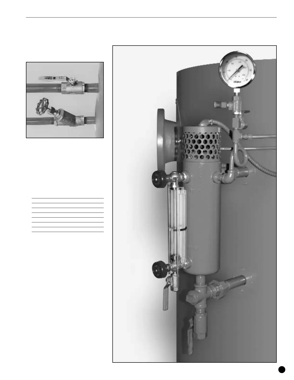
Blow-Down Valve
There are four blow-down valves on the
boiler: Two main bottom blow-down valves,
the gauge glass blow-down valve, and the
water column blow-down valve. All blow-
down connections must be piped to blow-
down seperator.
Feed Water Piping
1. Provisions must be made for adequate
water supply and properly sized piping.
Piping must be done in compliance with
all local codes. The following chart may
be used as a guideline for sizing.
BHP Minimum Water
Supply Piping Size
IN MM
40 1 25
50 1 25
60 1 25
80 1 25
100 1.25 31.7
130 1.25 31.7
150 1.25 31.7
2. When feeding the boiler using a return
system, the city water pressure should
not exceed 40 PSI. A pressure reducing
valve should be installed a head of the
return tank when above this pressure.
3. It is important that all piping be lined up
and not forced into place. It is
recommended that you begin piping at
the pump. If the lines are ended at the
pump, particularly if the last piece is cut
too short or long, the pump will be forced
to meet the pipe and strain or distortion
will result.
4. Do not use the pump as a piping
support. It is critical that the pipe be
independently supported near the pump
so no strain will be transmitted to the
unit.
5. Connect the feed water stop valve to the
feed water pipe at the rear of the boiler
and pipe it to the return system.
Water Column
Install the piping from the water column and
water gauge glass to a safe blow-down point.
Installation