28
VMP IOM
5. The end of the linkage arm that goes to
the gas valve will have a notch on both
sides of where the swivel collar should
be centered. This setting was based on
factory test fire conditions.
6. Combustion analysis should be done at
the installation to make any changes to
insure proper combustion characteristics.
7. To adjust the linkage, unscrew the
swivel collar and move the linkage rod in
the appropriate direction. The high-low-
off configuration comes with two
operating pressure controls.
8. Set the low operating pressure control to
approximately 60% of your desired set
point and the main operating pressure
control to your desired set point.
WARNING
Prior to the commencement of any work
requiring the removal of cover plates
and the opening of the control panel
box, the electrical supply to the boiler
must be disconnected.
Primary Air Adjustment
for Fulton Gas Fired
Steam Boilers
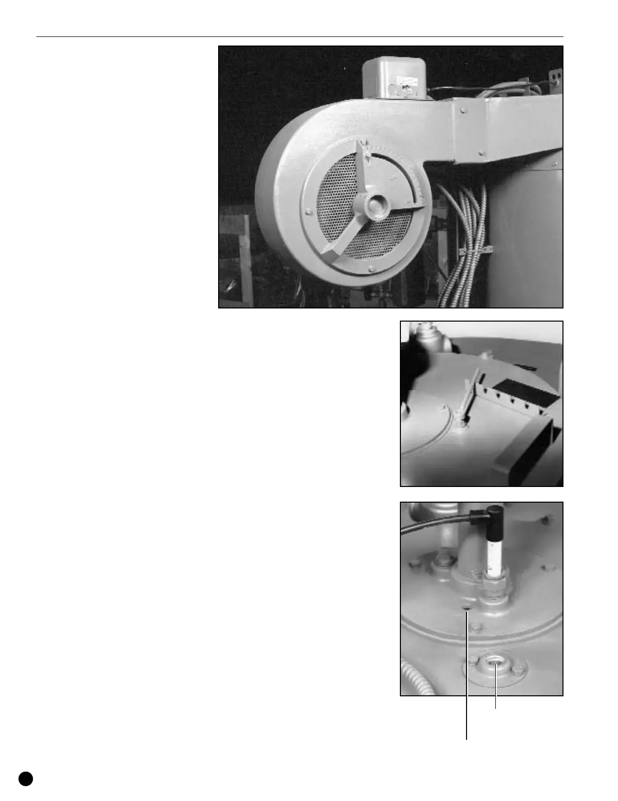
1. The primary air adjustment or main air
control is located at the fan housing
face. This control is used to supply the
burner with excess air needed to
facilitate good combustion. Too much or
too little air will result in poor
combustion. It is important to make sure
the lowest level of excess oxygen is
present while still maintaining a high
level of carbon dioxide and negligible
carbon monoxide. Using a CO
2
or O
2
tester it is possible to determine the
percent of excess air in the combustion
mixture.
2. It is a good policy on a gas fired unit to
have between 3.5% and 4% oxygen
present in the combustion. This will give
you 10.5% to 9.5% carbon dioxide. The
carbon monoxide level should always
be less than 400 PPM.
Secondary Air Adjustment
Procedure for Fulton Gas
Fired Steam Boilers
1. The secondary air control adjustment is
located on the top, right-hand side of the
burner assembly. This damper type air
controller is used to introduce air to and
through the blast tube of the burner. The
purpose of the secondary air adjustment
is to proportionately divide the air to the
center or outer fire chamber. By moving
the damper closed, the air is forced to
the outside of the fire chamber with less
air going down the blast tube area. By
pulling the damper open more air is
forced down the blast tube and less on
the outside wall of the deflector face and
fire chamber.
2. It is important in the combustion process
to maintain proper air mixtures between
the outer surface and center of the blast
tube area. On most boilers the damper
is locked in a wide open position.
However, if it is necessary to close the
damper, care should be taken to close
the damper slowly and no more than
1
/4
of the distance of the swing of the
damper assembly.
3. A visual examination down the blast
tube should reveal that no heat, flames
or fumes are backing up through the
burner plate area. If they are, the
secondary damper must be opened up
once again. Failure to remove the flame
or gases from the blast tube area can
cause a backfire as well as cause
premature failure of electrodes, flame
rods, and other burner components.
4. A visual inspection down the burner
view port should also show the fire
completely covering the furnace walls. If
the fire is tunneling down or is not to the
outside wall of the furnace, the efficiency
will drop off. Close the secondary air
damper until tunneling stops.
Operation
Primary Air Adjustment
is located at the fan
housing face.
Blast Tube
Viewing Port
Burner
Viewing Port
Secondary Air Adjustment