38
Pilot Adjustment for
Fulton LoNOx Burner.
1. Close downstream shut off valve.
2. Start boiler and check flame signal on
pilot, lock programmer into pilot hold.
3. Adjust air and gas regulator as needed
to obtain a strong pilot signal.
4. Slowly open downstream shut off valves
and take the flame programmer off of hold.
Main Flame Adjustment
For LE Models
1. Place a combustion analyzer in the
exhaust of the boiler.
2. Do not adjust main gas regulator. To
increase fuel to the burner, the servos
that control modulating gas valves
require adjustment.
Burner Tile Replacement
For LE Models
1. Remove scroll assembly.
2. Break off top holding clips.
3. Remove ceramic fiber burner tile.
4. Replace burner tile bottom holding clips
if needed.
5. Replace with new burner tile.
6. Carefully replace scroll assembly so that
the ceramic fiber burner tile is not
damaged.
Servo Motor Replacement
For LE Models
If it is determined that a servo motor needs to
be replaced, the first step in this process is to
verify the model number of the new servo
motor is the same as the old servo motor.
The model number starts with the letters SQM
and is displayed on a label on the side of the
motor. Once the new motor has been verified
to be correct, turn power to the boiler off.
1. Turn off all electricity to the boiler.
2. Remove the cover on the servo motor to
be changed.
3. Remove the green wiring plugs and the
conduit termination point from the motor
by pulling them towards you. A black
grounding wire runs from the motor to
the conduit termination point. Pull it off
from the conduit termination point.
4. Also note the location of the jumper on
the left side of the motor.
5. Loosen the allen screws on the motor
end of the motor to valve coupling.
6. Unbolt the motor from the mounting
bracket and remove the motor.
7. Turn the valve so it is in the closed
position and can rotate clockwise to open.
8. Mark the coupling or valve shaft if
needed so the position of the valve can
be determined when the servo motor is
installed.
9. Bolt the new servo motor on to the
mounting bracket with the motor shaft
inserted into the coupling.
10. Rotate the valve shaft/coupling assembly
closed as stated above.
11. While holding the valve closed, tighten
the allen screws on the coupling.
12. Install the wired green wiring plugs and the
conduit termination point on the new motor.
Connect the black grounding wire from the
motor to the conduit termination point.
13.Verify the jumper on the motor is located
on the same pins as the motor that was
replaced.
14.Turn power to the boiler on.
15.The screen will display ‘system test’.
The fault “Fault Feedback Air Actuator’
will be displayed. DO NOT RESET
THIS FAULT YET. Press Escape twice
to clear the fault from the screen.
16. Press Escape to get to the main menu.
Under Params&Display > Actuators >
Addressing, select either the gas actuator
or air actuator depending upon which was
replaced. The control will run an actuator
check then display ‘Start Address
Assignment with ENTER’. Press Enter.
The display will then have you press the
addressing button on the actuator. This is
the red button on the actuator. The screen
will then display ‘Actuator Address
Assignment Successful’.
17.Press Escape until the main menu is
reached. Under OperationalStat >
Status/Reset, reset the fault.
CAUTION
The boiler emissions may not be correct
after changing the servo motor. Verify the
emissions throughout the range of
modulation. If emissions are off, the
servo motor can be adjusted by following
the procedure in the Commissioning the
Boiler section of this manual.
18. Attach cover to servo motor.
Recommended Daily
Maintenance Schedule
The following procedures should be carried
out daily. They are designed to prevent the
build up of scale, silt, or sludge in the bottom
of the boiler and in the pipes leading to the
water gauge. In addition to these procedures,
the advice of a water treatment supplier
should be sought and followed. An ASME
Section VIII blow-down receptacle must be
provided for the appropriate pressure.
1. Blow down the boiler each morning by
starting the boiler and generating not
more than 10 PSI (.703 kg/cm
2
) of
steam. Turn on tap water to blow-down
separator, then open the boiler blow-
down valves for approximately 10
seconds, then close the valve. Shut off
tap water to blow-down separator.
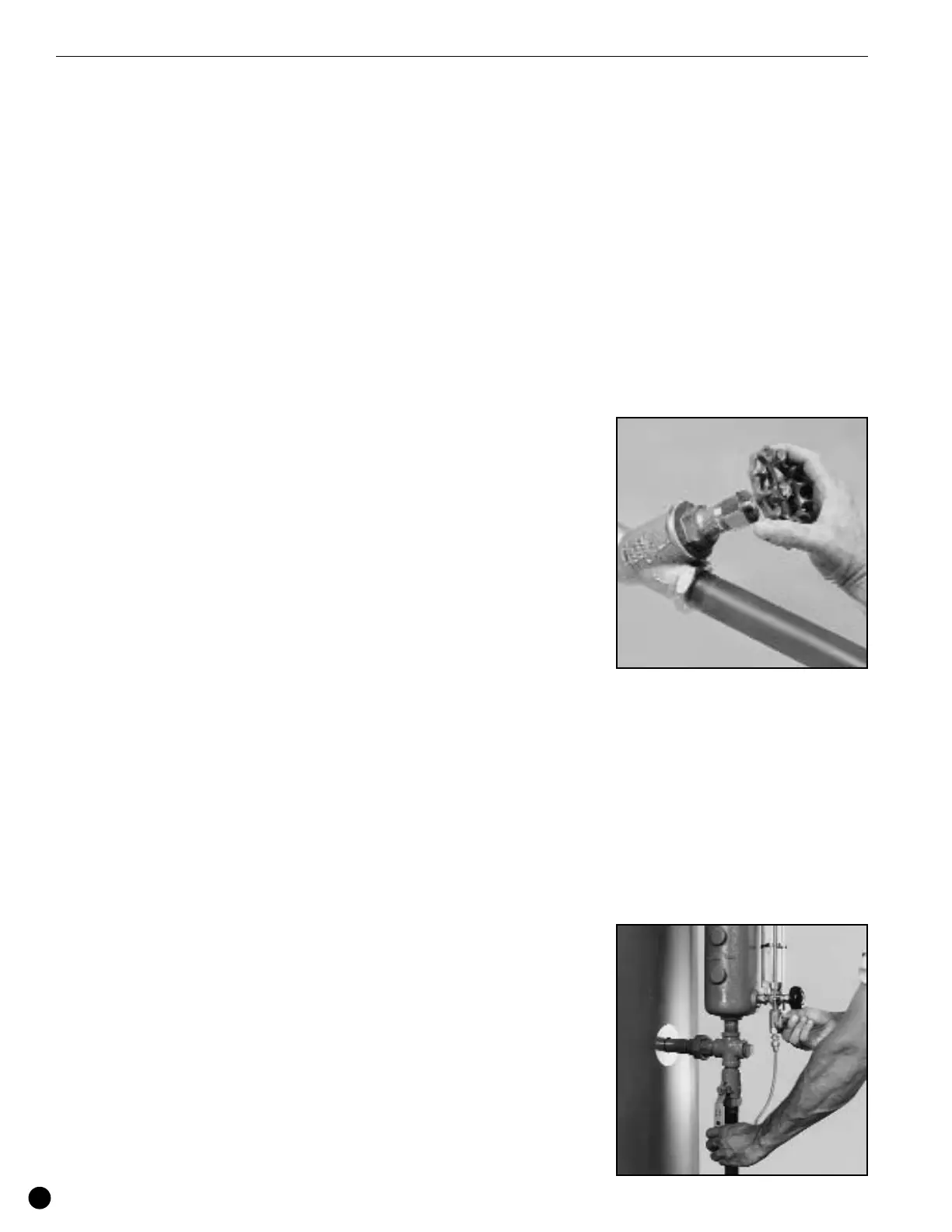
Blow Down Boiler Daily. Shown is the
blow down "Y" valve.
NOTE
If the boiler is being operated
automatically on a time clock, the blow-
down operation may be done once
during the working day and once at the
end of the day when at 10 PSIG or less.
2. Blow down water column each morning
when boiler is at 10 PSI (.703 kg/cm
2
) by
opening the water column and the water
gauge blow-down valves for approximately
5 seconds, then close the valves.
VMP IOM