2. WIRING
2-52
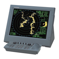
2. Remove the cable clamp from the control unit, then disconnect the control unit ca-
ble from the J1 connector.
3. Pull out the control unit cable from the cover.
4. Pass the optional cable assy (6TPSH-XH12X2-LxxSP2) through the cable hole on
the cover.
5. Fasten the shield part of the cable assy with the cable clamp (removed at step 2),
then connect the connector at the end of the cable assy to the J1 on the control
unit board.
Note: When clamping, the shield part of the cable must not touch the circuit board.
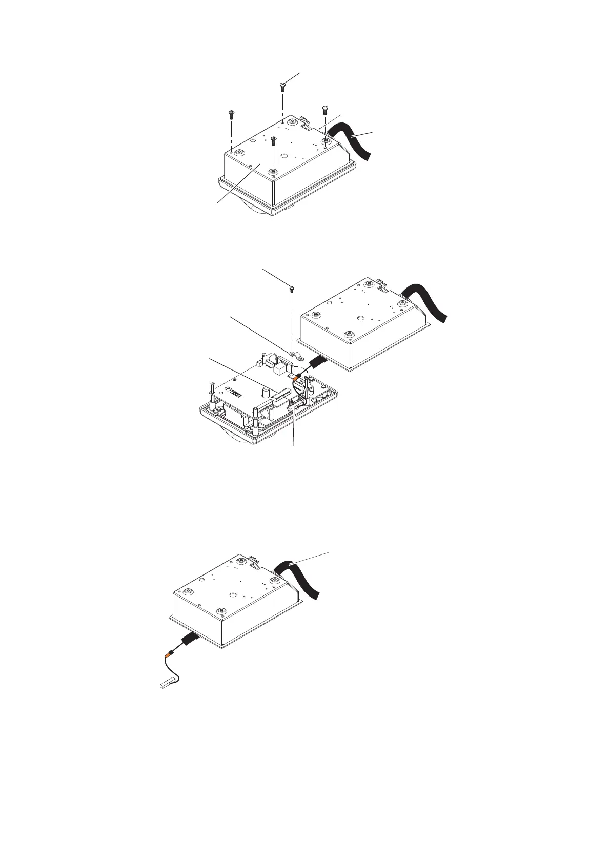
Binding screw (M3x8)
Control unit
cable
Control unit cover
Pan head screw
and flat washer
Cable clamp
Disconnect this connector.
J1 connector
Binding screw
Cable assy
(6TPSH-XH12X2-LxxSP2)