2. WIRING
13
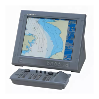
2.3 Display Unit
Remove four screws to remove the rear cable cover. Remove the cable clamps to con-
nect the cables.
Rear view of the display unit
Three cables are connected to the display unit. After connecting cables, close the ca-
ble cover.
• Cable for the transceiver unit (DPYC-1.5): To CN1
• Cable for the transceiver unit (TTYCSLA-4): To CN2
Connect the ground wire with the wing nut as shown the below.
• Cable from the printer (TPYCSLA-1.5): To CN3
Grounding
Shorten the ground wire as much as possible.
Note 1: Ground the equipment to prevent mutu-
al interference.
Note 2: Use “closed-type” lugs to make the
ground connection at the display unit and the
matching box. Do not use “open-type” lugs when
a crimp-on lugs are supplied locally.
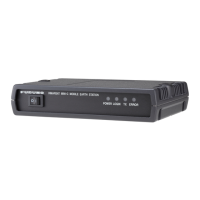
2.4 Transceiver Unit
1. Remove six screws to open the cover
of the transceiver unit.
Cable coverCable cover
DISP board
12P1004
DISP board
12P1004
Cable clampCable clamp
From printerFrom printer
From Transceiver unit
(For signal)
From Transceiver unit
(For signal)
From Transceiver unit
(For power)
From Transceiver unit
(For power)
CN3
CN2
CN1

 Loading...