44
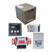
2.8 VHF Interface Unit
Two VHF audio signals may be connected to the terminal board in the DCU. IMO requires one
VHF audio to be recorded. A dual twisted, balanced cable carries the following signals:
+: 24 VDC (+)
A: Audio signal line, balanced, 0 dBm
B: Audio signal line, balanced, 0 dBm
-: 24 VDC (-)
The VHF interface unit mixes VHF transmitting and receiving signals for the VDR. When the VHF
outputs the mixed signal, this unit is not required.
Specifications
Power Supply: 24 VDC (21.6 to 31.6 VDC), 40mA
Mic input level: -16 to –56 dBm, Input impedance: >10k ohms
(Factory default: -46 dBm, 600 ohms: 10dB ATT ON)
Speaker input level: 32 to 200 ohms, 2 mW, input impedance: 10k ohms
(Factory default: 2 mW, 200 ohms: 10dB ATT OFF)
PTT Switch signal: TTL level
Output: 0 dBm±10dB, 600 ohms, balanced
When a wing handset is used, the connection is made as follows.
OUT1**
OUT2**
CN9
CN2
CN1
CN6CN5
CN7
CN3
CN4
CN8
*
DC24V
TTYCS-1
TTYCS-1
TB12
TB13
VR-3000 DCU
IF-5200
HANDSET
*
TTYC-4S
*
*
FM10PS-6H
FM14-7P
CC490, 1m
CC491, 1m
HANDSET
WING
HANDSET
FM-8700
**: OUT2 can be mixed with OUT1.
*: Connect one of OUT1 or OUT2. Fix cable with a cable tie
inside of the chassis.
X2
WING
HANDSET
Connecting FM-8700 to DCU via interface unit IF-5200

 Loading...