35
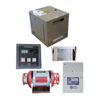
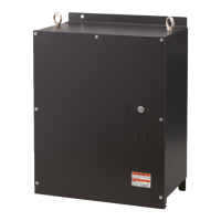
2.4 Junction Box
Connect the junction box to the DCU before turning on the system.
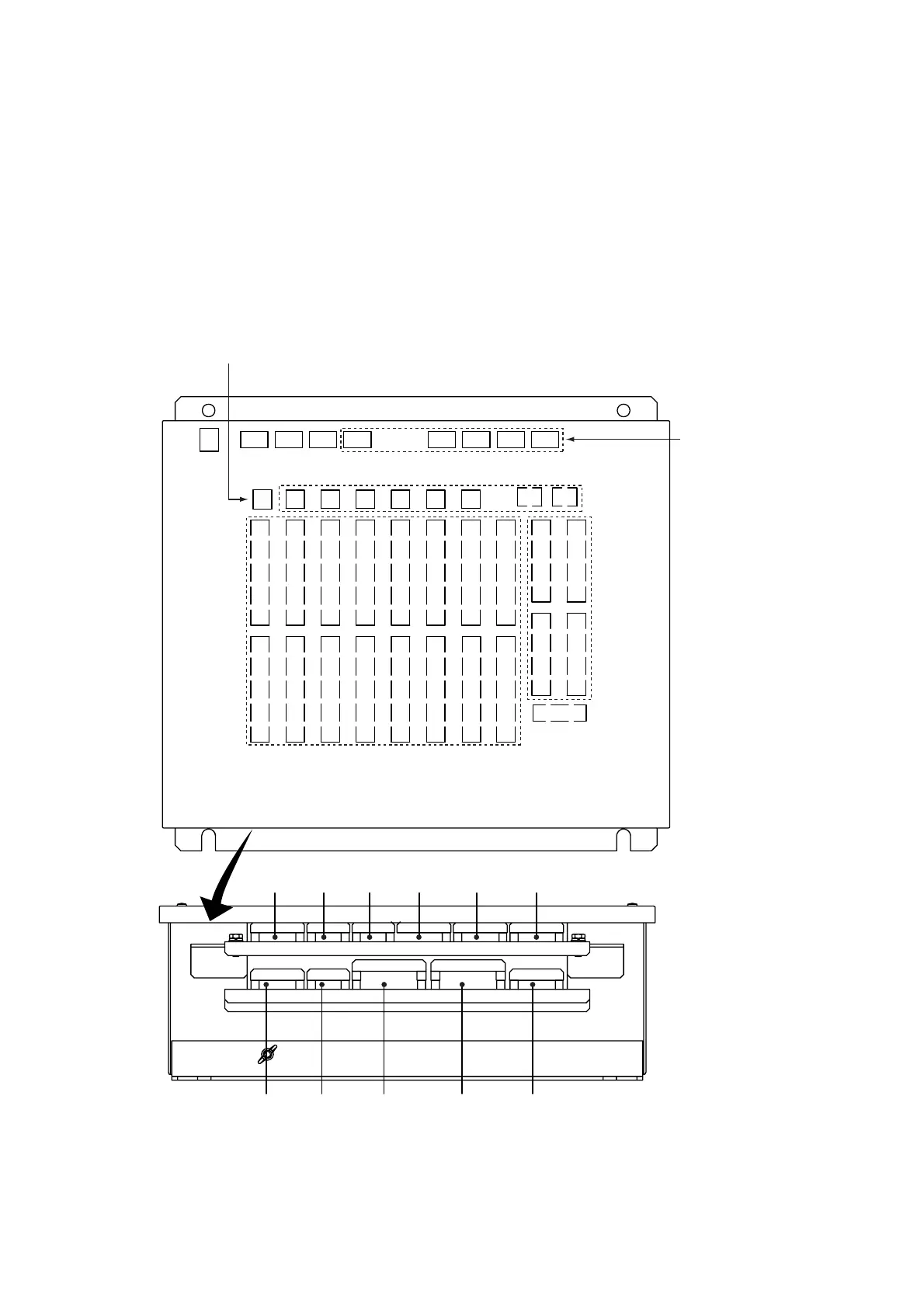
2.4.1 Location of connectors
Navigation device, etc. are connected to the terminals and connectors on the terminal board in
the JB. The terminal board has WAGO spring-catch terminal blocks for leads of up to 2.5 mm
2
or
AWG 14 wires.
Insert wires into holes in the connectors the same as on the terminal board in the DCU.
SERIAL CHANNELS
ANALOG
CHANNELS
DC 24V IN
DIGITAL
CHANNELS
CH1-CH4 CH5-CH8
CH9-CH12 CH13-CH16
CH17-CH20 CH21-CH24
CH25-CH28 CH29-CH32
CH33-CH36 CH37-CH40
CH41-CH44 CH45-CH48
CH49-CH52 CH53-CH56
CH57-CH60 CH61-CH64
CH3 CH4 CH5 CH6 CH7 CH8 CH1 CH2
CH1-CH4 CH5-CH8
CH9-CH12 CH13-CH16
DCU
DIP SW from left:
S5 (JB No.)
S4 (Baud Rate)
S3 (Baud Rate)
S2 (Analog)
S1 (Analog)
Power SupplyAnalogSerialSerialLANSerial
Spare Spare Digital Digital Analog
SERIAL OUT CH1 (for additional JB)
CH1
Location of connectors inside the junction box, where to lead in cables thru cable clamps

 Loading...