12
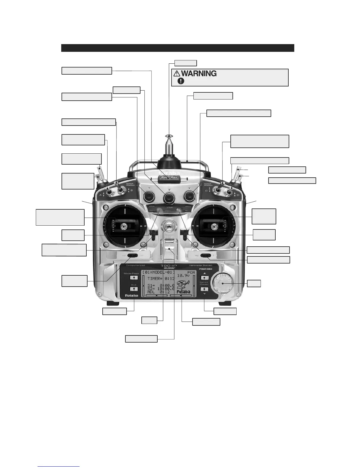
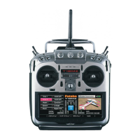
This figure shows the default switch assignments for a 9CH super Mode 2 system as supplied by the factory.
You can change many of the switch positions or functions by selecting a new position within
the setting menu for the function you wish to move. (Example: move aileron dual rates to switch C
to create triple rates. See p. 35 for details.)
* Power LED blinks to indicate if any mix switches are activated.
** RF LED is blue when the transmission link is solid and the radio is transmitting properly.
CAMPac or Dust Cap
TRANSMITTER CONTROLS - HELI
SW(B)
VR(A)
VR(B)
SW(A)
SW(F)
SW(E)
VR(D)
VR(E)
VR(C)
SW(G)
SW(H)
SW(D)
SW(C)
CH8 Knob
Hovering - Pitch Knob
Rudder Dual Rate Switch
Elevator Dual Rate
Switch
Idle-up 3 Switch
Idle-up 1&2
Switch
Throttle/Collective
Pitch & Rudder Stick
Throttle/Collective
Trim Lever
Power
LED*
Rudder
Trim Lever
LCD Panel
Power Switch
(Up position: ON)
Hook
(for optional neckstrap)
Edit Keys
Edit keys
Aileron Trim Lever
Dial
Elevator Trim Lever
Elevator
/Aileron
Stick
Aileron Dual Rate Switch
Throttle - Hold Switch
Trainer Switch
CH 7/Governor Switch
Hovering - Throttle Knob
Carrying Handle
Antenna
Antenna must be fully extended when flying.
Be careful not to bend your antenna when you
collapse or extend it.
LED**
RF