31
< BeforeUse >
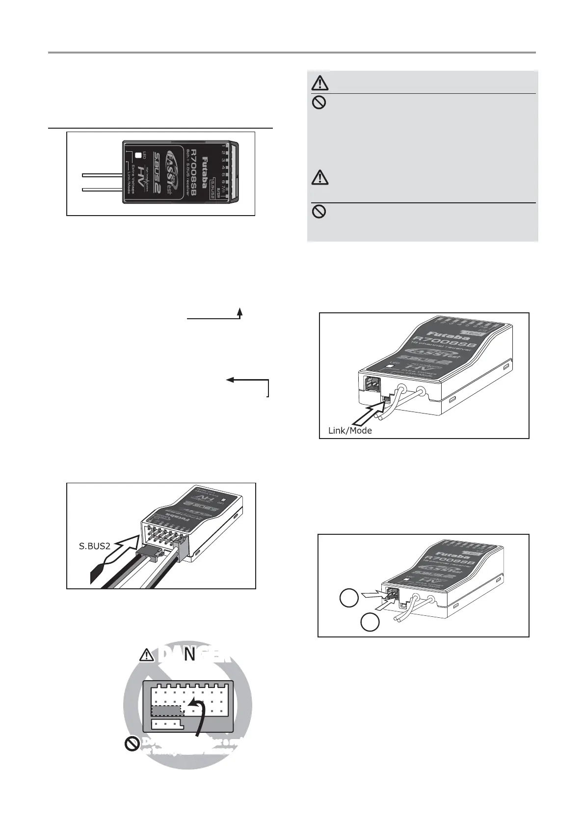
Link/Mode Switch
8se the small plastic screw driver that was
included with your receiver.
The /ink/Mode Switch is also used for the CH
mode selection.
Extra Voltage Connector
8se this connector when using a voltage
telemetry device to send the battery voltage DC
a 9 from the receiver to the transmitter.
<ou will need to purchase the optional
(xternal 9oltage input cable CA-R9I1-.
<ou can then make a cable with an extra
connector to the (xternal voltage connector.
%efore using the receiver be sure to read the
precautions listed in the following pages.
ŵƈƆƈƌƙƈƕŃŵŚœœśŶť
Connector
through 6: outputs for the channels
through 6
/%: outputs of channels and power.
/S%: outputs of channels or S.%8S port.
>S.BUS Servo S.BUS *yro @
*:hen using /S% as S.%8S you have to set
CH M2D( of the following page to mode % or
mode D.
S.%8S2: outputs of S.%8S2 port.
>S.BUS2 Servo S.BUS2 *yro Telemetry Sensor @
*:hen using or more channels use an S.%8S
function or use a second RS% and link
both to your transmitter.
*CG< S.%8S Gyro should 12T be
connected to the S.%8S2 ports on any receiver.
Connector insertion
Firmly insert the connector in the direction
shown in the ¿gure. Insert the S.%8S2 by turning
it degrees.
+
−
Do not connect either a switch
or battery in this manner.
Do not connect either a switch
or battery in this manner.
5HFHLYHU
DANGERDANGER
DANGER
Don'tattachaconnectorasshownin
theprecedingillustration.
*Itwillshort-circuitifconnectedinthisway.A
shortcircuitacrossthebatteryterminalsmay
causeabnormalheating,fireandburns.
WARNING
S.BUS2connectors
Don'tconnectanS.BUSservo/gyro
toS.BUS2connector.
LED Monitor
This monitor is used to check the CH mode of
the receiver.
ŵƈƆƈƌƙƈƕŃƑƒƐƈƑƆƏƄƗƘƕƈ