17
M
OUNTING
/ P
ART
N
AMES
/ C
ONNECTING
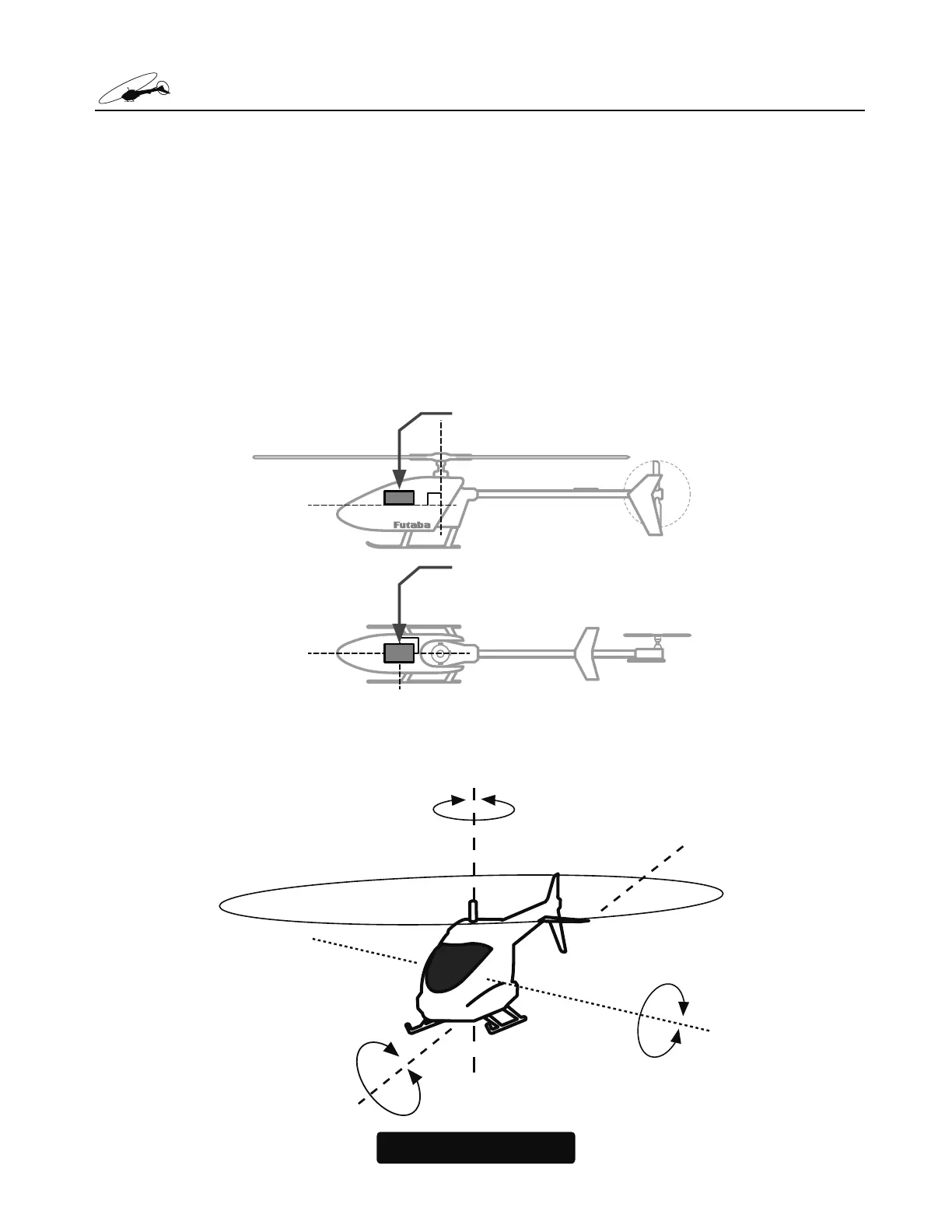
Mount on a model using the attached mounting pad and mount it at the center posi-
tion of model gyro mount so that it is exactly parallel to the roll and pitch axis of the
DLUFUDIW
7KH&*<5VKRXOGEHPRXQWHGRQDULJLGSODWIRUPDWOHDVWLQ>PP@DZD\IURPD1LWUR
(QJLQH ,W LV QRW QHFHVVDU\ WR PRXQW WKH J\UR QHDU WKH PDLQ VKDIW RI WKH PRGHO EXW LW LV YHU\
LPSRUWDQWWKDW WKHPRXQWLQJDUHDFKRVHQLVULJLG3OHDVH UHIHUWR\RXUPRGHOPDQXIDFWXUHU¶V
LQVWUXFWLRQVIRUUHFRPPHQGHGPRXQWLQJORFDWLRQV
7HVW¿WWKHJ\URVHQVRUHQVXULQJWKDWWKHVHQVRULVLQDOLJQPHQWZLWKWKHPRGHORQWKHUROODQG
SLWFKD[LV 7KHFDEOHIURPWKHJ\URVHQVRU PXVWH[LWWRZDUGWKHIURQW RUWKHUHDURIWKHPRGHO
VLQFHWKLVLVWKHSLWFKD[LV$Q\PLVDOLJQPHQWZLOOFDXVHDORVVRISHUIRUPDQFH
Mounting angle
• The bottom of the CGY760R Gyro Sensor must be
perpendicular to the main shaft.
•The roll axis must be parallel to the tail boom and
the pitch axis must be perpendicular to the side
frame.
Control axis
• Elevator (Pitch) axis
• Rudder (Yaw) axis
• Aileron (Roll) axis

 Loading...
