Parameter
Description
Parameter
Description
Range
Default
Value
Default
Value
Contained
in
Contained
in
Basic
Function
Basic
F
unction
Parameter
Notation
Parameter
Notation
Display
Format
Display
F
ormat
4
5
6
7
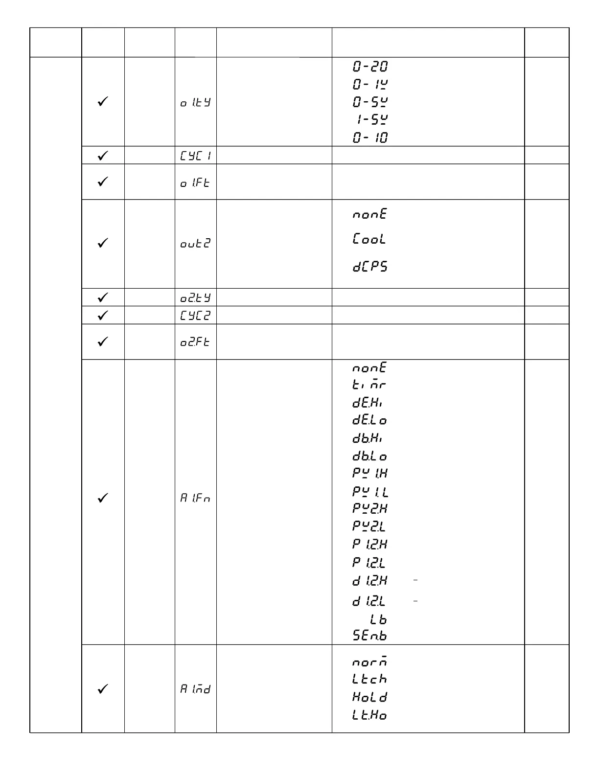
0 - 20 mA current module
0 - 1V voltage module
0 - 5V voltage module
1 - 5V voltage module
8
0 - 10V voltage module
:
:
:
:
:
CYC1
O1TY
Output 1 Cycle Time
100.0 sec 18.0
0
0.1
Low:
High:
O1FT
Output 1 Failure Transfer
Mode
Select BPLS ( bumpless transfer ) or 0.0 ~ 100.0
% to continue output 1 control function as the unit
fails, power starts or manual mode starts.
Select BPLS ( bumpless transfer ) or 0.0 ~ 100.0
% to continue output 2 control function as the unit
fails, power starts or manual mode starts.
BPLS
Output 2 Function
OUT2
0
0
1
2
: PID cooling control
: Output 2 no function
: DC power supply module
installed
O2TY
CYC2
O2FT
Output 2 Signal Type
Output 2 Cycle Time
Output 2 Failure Transfer
Mode
100.0 sec
BPLS
18.0
0
0.1
Same as O1TY
Low:
High:
A1FN
Alarm 1 Function
2
6
IN1 process value high alarm
:
9
IN2 process value low alarm
:
0
No alarm function
:
4
Deviation band out of band alarm
:
1
Dwell timer action
:
5
Deviation band in band alarm
:
8 IN2 process value high alarm
:
3
Deviation low alarm
:
2
Deviation high alarm
:
11
IN1 or IN2 process value low
alarm
:
7 IN1 process value low alarm
:
10
IN1 or IN2 process value high
alarm
:
12
IN1 IN2 difference process value
high alarm
:
13
IN1 IN2 difference process value
low alarm
:
:
:
14 Loop break alarm
15 Sensor break or A-D fails
:
:
:
:
1
2
3
0
Normal alarm action
Latching alarm action
Hold alarm action
Latching & actionHold
A1MD
Alarm 1 Operation Mode
0
Table 1.6 Parameter DescriptionTable 1.6 Parameter Description
Setup
Menu
Output 1 Signal Type
UMA83001A-August-2024
11