Stay at least minutes in still-
air room
room temperature 25 3 C
20
AL
Stay at least minutes in still-
air room
room temperature 25 3 C
20
AL
Perform step 10 to calibrate of compensation, if
required.
The
DIP switch is set for T/C input.
offset cold junctionPerform step 10 to calibrate of compensation, if
required. The DIP switch is set for T/C input.
offset cold
junction
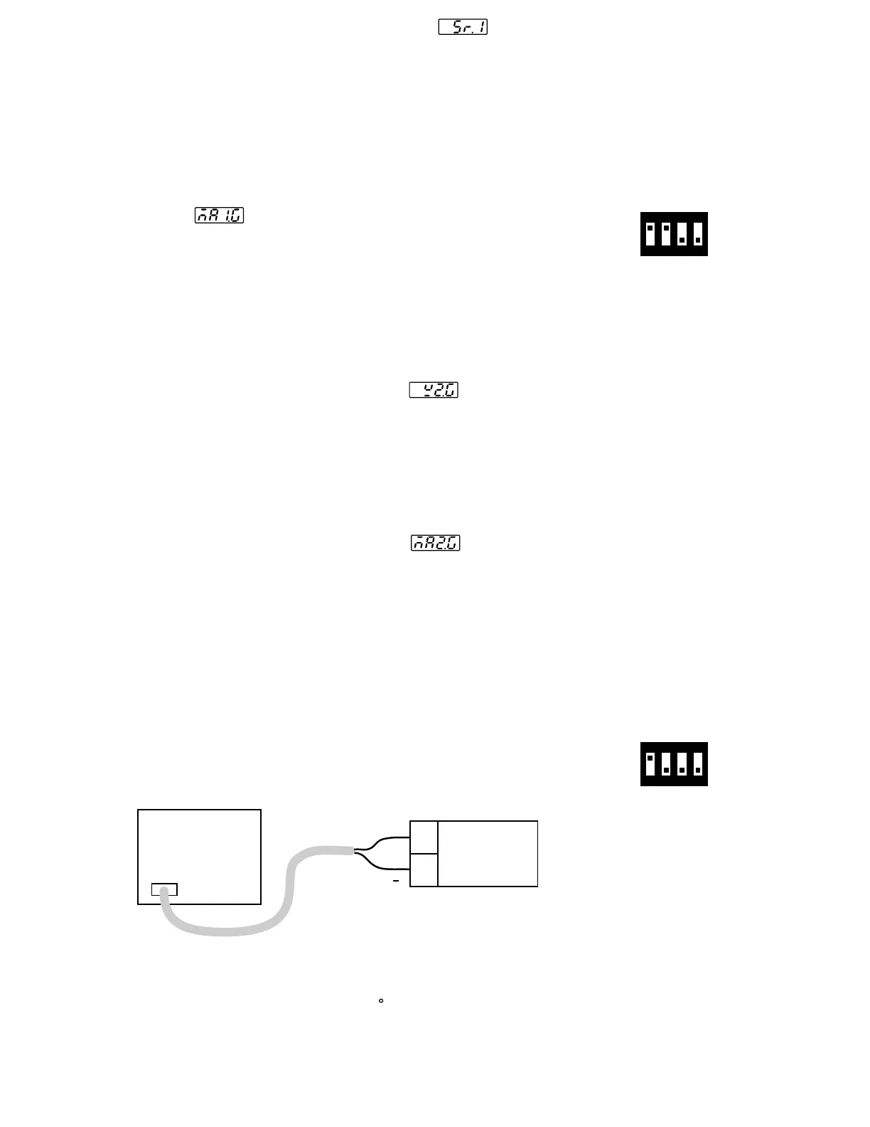
Setup the equipments according to the following diagram for
calibrating
the
cold junction compensation. Note that a K type
thermocouple must be used.
Setup the equipments according to the following diagram for
calibrating the cold junction compensation. Note that a K type
thermocouple must be used.
Step 10.Step 10.
Press scroll key and the display will show . Change the
ohm's value to 300 ohms .Press scroll key for at least 3 seconds.
The display will blink a moment and two values are obtained for SR1
and REF1 (last step). Otherwise, if the display didn't blink or if any
value obtained for SR1 and REF1 is equal to -199.9 or 199.9 ,
then the calibration fails.
Perform step 7 to calibrate function ( if required ) for input 1.mAPerform step 7 to calibrate function ( if required ) for input 1.mA
Change the DIP switch for mA input. Press scroll key until the display
shows
.Send
a 20 mA signal to terminals 19 and 20 in
correct polarity. Press scroll key for at least 3 seconds . The display
will blink a moment and a new value is obtained . Otherwise , if the
display didn't blink or if the obtained value is equal to -199.9 or 199.9,
then the calibration fails.
Change the DIP switch for mA input. Press scroll key until the display
shows .Send a 20 mA signal to terminals 19 and 20 in
correct polarity. Press scroll key for at least 3 seconds . The display
will blink a moment and a new value is obtained . Otherwise , if the
display didn't blink or if the obtained value is equal to -199.9 or 199.9,
then the calibration fails.
Perform step 8 to calibrate as well as CT function ( if required )
for
input
2.
voltagePerform step 8 to calibrate as well as CT function ( if required )
for input 2.
voltage
Press scroll key until the display shows . Send a 10 V signal to
terminals 15
and 16 in correct polarity. Press scroll key for at least 3
seconds . The display will blink a moment and a new value is obtained .
Otherwise , if the display didn't blink or if the obtained value is equal
to -199.9 or 199.9 , then the calibration fails.
Press scroll key until the display shows . Send a 10 V signal to
terminals 15 and 16 in correct polarity. Press scroll key for at least 3
seconds . The display will blink a moment and a new value is obtained .
Otherwise , if the display didn't blink or if the obtained value is equal
to -199.9 or 199.9 , then the calibration fails.
Press scroll key until the display shows . Send a 20 mA signal
to
terminal
15 and 16 in correct polarity. Press scroll key for at least
3 seconds . The display will blink a moment and a new value is obtained .
Otherwise , if the display didn't blink or if the obtained value is equal to
-199.9 or 199.9, then the calibration fails.
Press scroll key until the display shows . Send a 20 mA signal
to terminal 15 and 16 in correct polarity. Press scroll key for at least
3 seconds . The display will blink a moment and a new value is obtained .
Otherwise , if the display didn't blink or if the obtained value is equal to
-199.9 or 199.9, then the calibration fails.
Step 6.Step 6.
Step 7.Step 7.
Step 8.Step 8.
Step 9.Step 9.
*
*
Perform step 9 to calibrate function ( if required ) for input 2.mAPerform step 9 to calibrate function ( if required ) for input 2.mA
*
*
Figure 6.2
Cold Junction
Calibration Setup
Figure 6.2
Cold Junction
Calibration Setup
FDC-8300
19
20
K+
K
5520A
Calibrator
5520A
Calibrator
K-TC
The 5520A calibrator is configured as K type thermocouple output with
internal compensation. Send a 0.00 C signal to the unit under
calibration.
The 5520A calibrator is configured as K type thermocouple output with
internal compensation. Send a 0.00 C signal to the unit under
calibration.
1 2 3 4
ON
1 2 3 4
ON
DIP Switch PositionDIP Switch Position
mA inputmA input
DIP Switch PositionDIP Switch Position
TC inputTC input
UM83001A-August-2024
40