Page 12 of 35
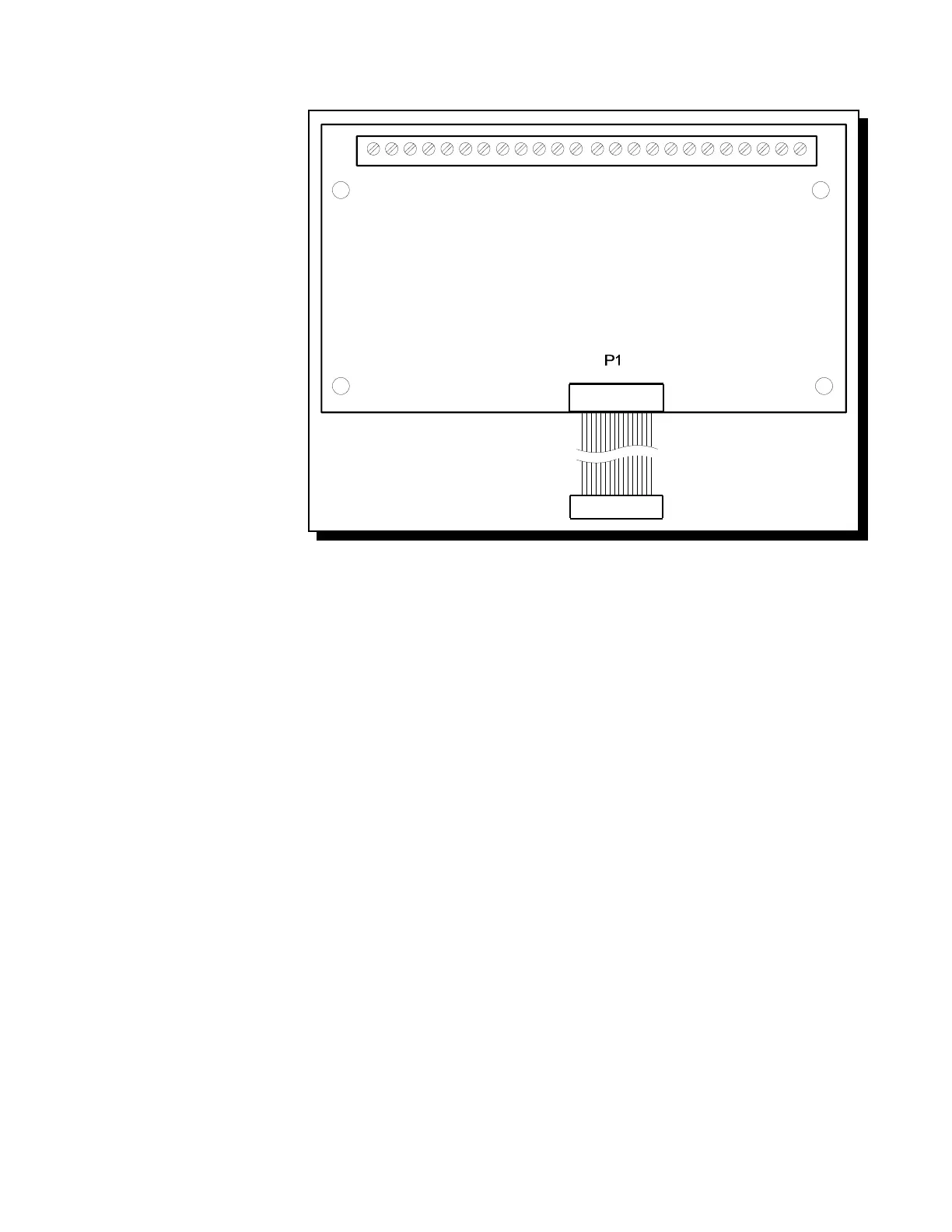
Fig.5: RY4 or RY8 Auxiliary Relay Module
6.3 RELAY MODULES (Models RY4 or RY8)
P1 Connect to P1 on the Main
Fire Alarm Board.
By the factory setting, the 4 or 8
relays are controlled by Initiating
Circuits 1 to 8 respectively. This is
configured by selecting ...
JW1 Initiating Circuit #1 controls
Relay #1.
JW2 Initiating Circuit #2 controls
Relay #2.
|
|
JW8 Initiating Circuit #8 controls
Relay #8.
Alternatively, each relay may be set
as a Common Alarm or Common
Supervisory Relay by moving the
jumper from JW1 to JW1A, etc.
These jumpers have two positions to
select Alarm or Supervisory each.
JW1A Alarm or Supv. control for
Relay #1.
JW2A Alarm or Supv. control for
Relay #2.
|
|
JW8A Alarm or Supv. control for
Relay #8.
Finally, there are jumpers JW1.2, JW2.3, up to JW7.8 that allow a relay to have the same control as an adjacent relay. For example, starting with
the factory default setting, moving the jumper from JW2 to JW1.2 will make both Relays 1 & 2 operate with Initiating Circuit #1.
Contact GAMEWELL Technical Services for assistance if required.
Technical Manuals Online! - http://www.tech-man.com