Page 21 of 35
7.8 WIRING TABLES
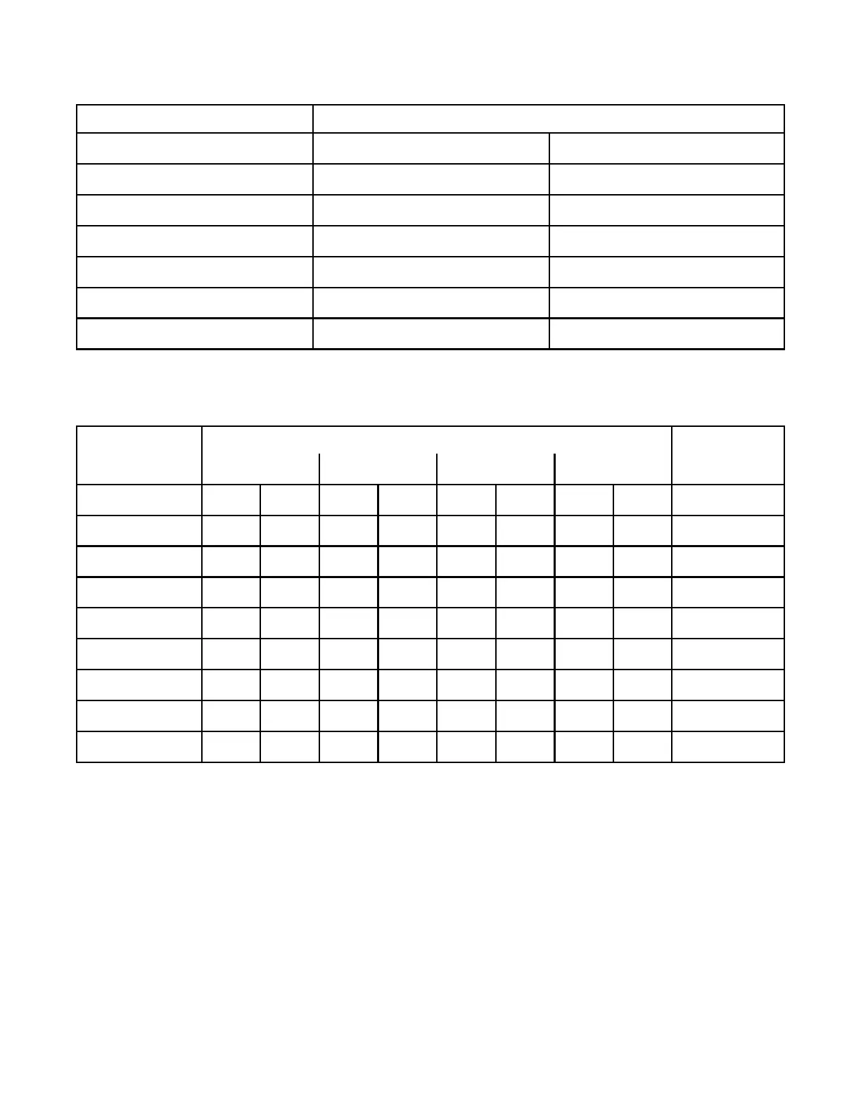
Fig.14: WIRING TABLE FOR INITIATING CIRCUITS
WIRE GAUGE MAXIMUM WIRING RUN TO LAST DEVICE (ELR)
(AWG) ft m
22 2990 910
20 4760 1450
18 7560 2300
16 12000 3600
14 19000 5800
12 30400 9200
NOTE: MAXIMUM INITIATING LOOP RESISTANCE SHALL NOT EXCEED 100 OHMS
Fig.15: WIRING TABLE FOR INDICATING (NOTIFICATION APPLIANCE) CIRCUITS
TOTAL
SIGNAL LOAD
MAXIMUM WIRING RUN TO LAST DEVICE (ELR) MAX. LOOP
RESISTANCE
18AWG 16AWG 14AWG 12AWG
Amperes ft m ft m ft m ft m Ohms
0.06 2350 716 3750 1143 6000 1829 8500 2591 30
0.12 1180 360 1850 567 3000 915 4250 1296 15
0.30 470 143 750 229 1200 366 1900 579 6
0.60 235 71 375 114 600 183 850 259 3
0.90 156 47 250 76 400 122 570 174 2
1.20 118 36 185 56 300 91 425 129 1.5
1.50 94 29 150 46 240 73 343 105 1.2
1.70 78 24 125 38 200 61 285 87 1.0
RS-485 WIRING: See the Connection Diagram.
AUXILIARY POWER FOR The maximum allowable current is 0.15 Amperes. The maximum allowed
FOUR WIRE TYPE DETECTORS Voltage Drop is 1 Volt. Refer to the Indicating Circuit Wiring Table above
for wire run information. Be certain to verify the voltage at the last powered
initiating device is within its’ Listed operating voltage range. Use only
devices rated for operation on a 24 volt DC power source.
Technical Manuals Online! - http://www.tech-man.com