Stability in Potentiostat Mode – Improving Potentiostat Stability
56
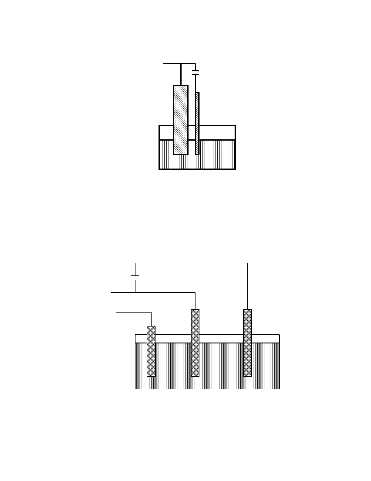
Figure 8-1
Fast Combination Reference Electrode
SCE Platinum
White
Cell Lead
100 pF to 10 nF
Electrolyte
• Provide a high-frequency shunt around the cell. A small capacitor between the red and white cell
leads allows high-frequency feedback to bypass the cell, see Figure 8-2) The capacitor value is
generally determined by trial and error. One nF (1000 pF) is a good starting point.
In a sense, this is another form of an AC-coupled low-impedance reference electrode. The counter
electrode is the low-impedance electrode, eliminating the need for an additional electrode in the
solution.
Figure 8-2
High Frequency Shunt
• Add resistance to the counter electrode lead, see Figure 8-3 This change lowers the effective
bandwidth of the control amplifier. As a rule of thumb, choose the resistor to give one volt of drop at
the highest current expected in the test being run. For example, if you expect your highest current to
be around 1 mA, you can add a 1 k resistor.