Chapter 6 -- Instrument Circuitry--Interface 1000 Schematic/Block Diagrams
6 - 2
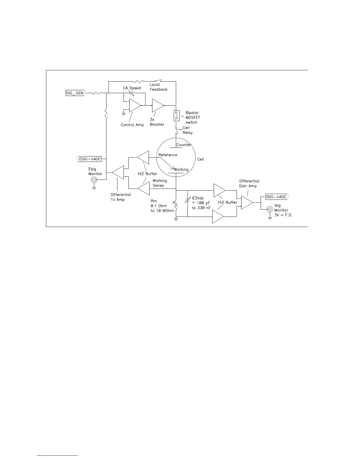
Figure 6-1
Interface 1000 Potentiostat Board in Potentiostat Mode
Notes for Figure 6-1
• Only Potentiostat Mode circuitry is shown in this figure. In this mode the voltage difference between the
Reference and Working Sense leads (called Esig) is fed back into the control amplifier.
In Galvanostat Mode, the feedback is from Isig. In ZRA mode, the feedback is from a differential amplifier
measuring the difference between the Counter Sense and Working Sense leads of the cell cable. The
counter sense circuitry is not shown. It is conceptually similar to the voltage sensing circuit that generates
Esig.
• Switches are either computer controlled reed relays or MOS switches as appropriate
• All components shown as being variable (resistance Rm, capacitor IEStab and capacitor CASpeed) are
actually several fixed value components switched into the circuit. They are not continuously variable as
implied in the figure.
• The monitor connections for Isig and Esig are filtered using an RLC circuit.
• All the resistors summing voltages into the Control Amplifier input do not have values shown – their values
depend on scaling factors too complex to discuss in this simplified diagram.
• Calibration components are not shown.
• Overload protection and overload detection are not shown. Good engineering practice demands that any
possible misconnection of the cell leads will not damage the instrument. This practice has been followed in
the Interface 1000 design.