Chapter 6 -- Instrument Circuitry--Interface 1000 Schematic/Block Diagrams
6 - 3
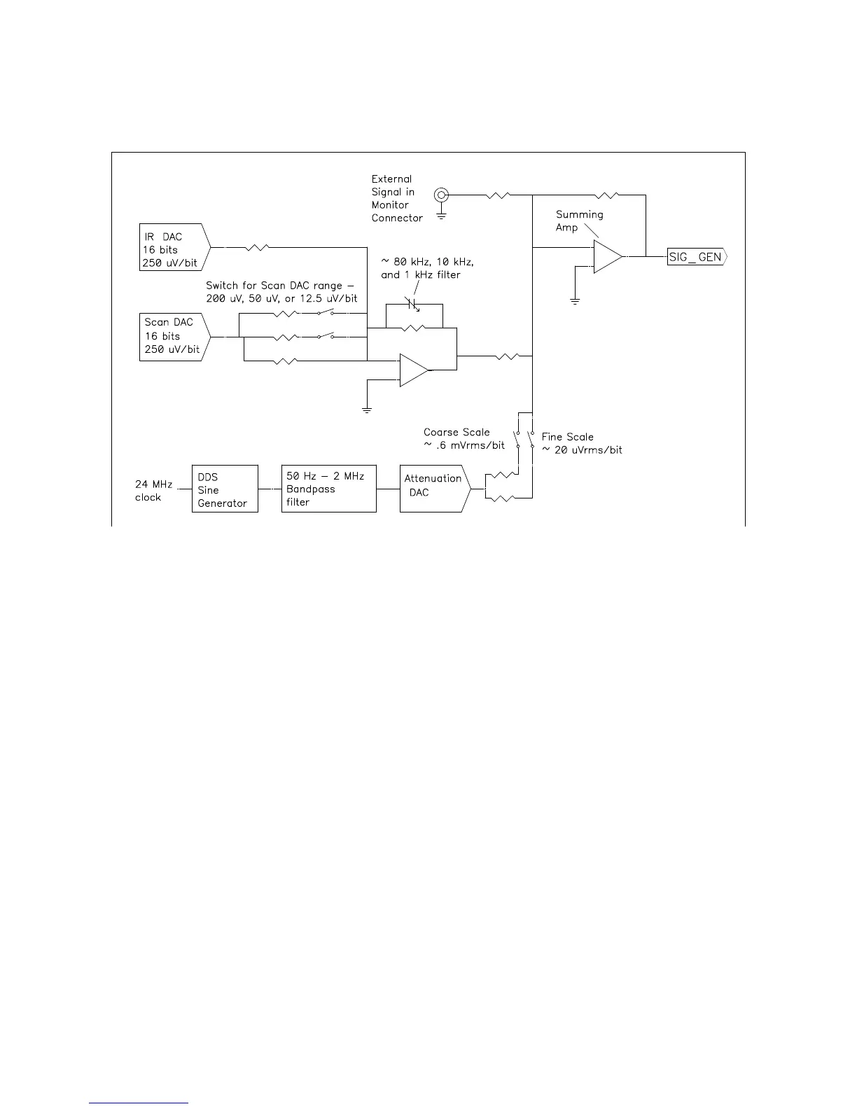
Figure 6-2
Interface 1000 Signal Generation Circuitry
Notes on Figure 6-2:
• All the resistors summing voltages into the Summing Amplifier input do not have values shown because
their values depend on scaling factors too complex for this simplified diagram.
• Calibration components are not shown.
• High frequency sine wave generation is done using a DDS (direct digital synthesis) IC. The DDS’s output is
filtered with both a high pass and low pass filter. The low pass filter removes the steps in the DDS output.
The high pass filter provides AC coupling to prevent drift in the DDS’s offset getting into the applied signal.
In practice, Gamry EIS300 software uses the DDS to apply sine waves with frequencies between 100 Hz to
1 MHz. It uses the Scan DAC to generate sine signals at frequencies below 100 Hz.
A two stage attenuator scales the DDS. On the coarse scale, the maximum output signal is 2.33 V
rms
(3.3
V
peak
) and the resolution is approximately 0.6 mV
rms
/bit. On the fine scale, the maximum is approximately
77 mV
rms
and the resolution is approximately 20 µV
rms
. AC signal attenuation is handled automatically by
Gamry software.
• The Scan DAC and Bias DAC signals are filtered before they are applied to the cell. The filter bandwidths
are as shown.