GAT NET.Lock 7020 System
Electrical Connections
44
HB_GAT-NETLOCK7020--EN_12
www.gantner.com
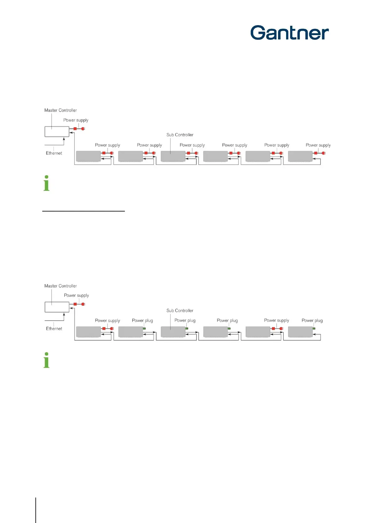
► For systems that do not have any GAT NET.Lock 7020 USB locks and are connected in series (see “4.4.2 Sub
Controller Connection”), connect one GAT NET.Power Supply 7020 100-240V / VI to each sub controller. As an
alternative for non-USB systems, the number of power supplies can be reduced as shown in option 2.
To calculate the requirements for an emergency power supply (UPS), allow for a typical power consumption of
3 W (+2 W reserve) per master controller and 90 W per sub controller fully connected with locks.
Option 2: Shared power supply
NOTE! This option is only suitable for systems that do not use any GAT NET.Lock 7020 USB locks.
► Connect one GAT NET.Power Supply 7020 100-240V / VI to the master controller and the first and fifth sub
controllers only. A power supply must always be connected to the master controller and the first sub controller.
If 5 or more sub controllers are used in one line, a second power supply is required at the fifth controller.
► For the sub controllers that are not directly connected to a power supply, insert one GAT NET.Power Plug
(included with the sub controller) into the power connector.
o The power is then forwarded on to the remaining sub controllers via the RS-485 line.
To calculate the requirements for an emergency power supply (UPS), allow for a typical power consumption of
3 W (+2 W reserve) per master controller and per sub controller fully connected with locks.
 Loading...