37-1-615 Page 43
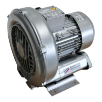
FIGURE 7-14
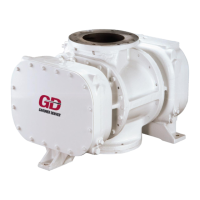
FIGURE 7-15
It is not recommended to hammer bearings of this size in place.
18. Install lockwashers (35, 36) and bearing retainer nuts (33, 34) on both shafts and drive up tight.
This operation pulls the rotor shaft through the bearings until the shaft shims and bearing
spacer are clamped solidly between the rotor end and bearing, assuring a fixed position of the
rotor. This is an important step in the assembly. The best method for tightening the nuts is
with a wrench of the type shown in Disassembly, Figure 6-3. Tighten the main rotor nut (33) to
230-250 ft-lb and tighten the gate rotor nut to 130-150 ft-lb.
Making sure the bearings are properly seated, measure the height the outer race of the main
rotor bearing (30) extends above the bearing carrier surface (5) with a depth micrometer.
Measure the height in at least four places around the circumference of the outer race. Establish
required shim thickness under the main rotor bearing retainer (12) by taking the average of the
measurements and subtracting 0.004” from the average measured height. (Required Shim
Thickness = Average Measured Height – 0.004”) Select a maximum of four shims from the
shim kit (94) as required to obtain the required calculated shim stack thickness at each screw
location. Using a micrometer, measure each stacked shim thickness to insure the thickness is
within +0.001/-0.000 of the required calculated thickness for each screw location. Install main
rotor bearing retainer (12) with the required shim stack between the bearing retainer and the
bearing carrier at each of the four “Nylok” type screw (47) locations. Tighten screws to
51-58 ft-lb.
Install bearing retainer plate (11) on the gate rotor with the four “Nylok” type screws (47),
Figure 7-18. Tighten screws to 51-58 ft-lb.
19. Check the discharge end clearance of the rotor with a feeler gauge through the discharge
opening, FIGURE 7-18. Also check rotor end clearance at the inlet end through the inlet
opening. Clearance should match those listed in the chart, FIGURE 7-8, keeping in mind the
allowable tolerance and possible .002” variation in rotor lengths. Never allow rotors to run
closer than allowable tolerance. Wider clearance will not result in blower failure but may affect
efficiency. If the discharge end clearance is too great, make sure the bearing retainer plate is
tight, holding bearing solidly against the end of the rotor, Step 18. If clearance is too close,
remove the discharge end carrier and repeat the steps to establish shaft shim sets and total end
clearance.
 Loading...