37-1-615 Page 8
SECTION 2
INSTALLATION
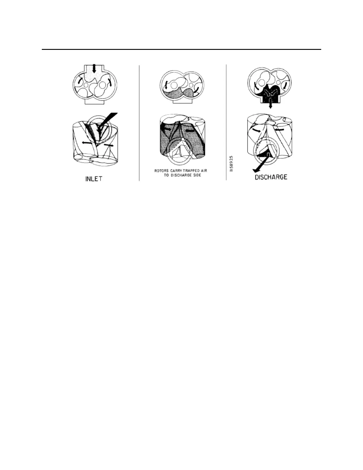
FIGURE 2-1 – OPERATING PRINCIPLE
GENERAL – The CycloBlower® is a compact, rotary lobe type axial flow blower/compressor. The
meshing of two screw type rotors synchronized by timing gears provides controlled compression of the air
for maximum efficiency and pulsation-free discharge.
OPERATING PRINCIPLE – Compression is effected by the main (2 lobe) and gate (4 flute) rotors
meshing enclosed in the housing. The timing gears maintain close rotor clearances. The rotors do not
touch each other, the housing, or the bearing carries. Although clearances are small, lubrication in the
compression chamber is not required, insuring oil-free air delivery.
The compression cycle (FIGURE 2-1) begins as the rotors unmesh at the inlet port. Air is drawn into the
rotor cavities, trapped, and compressed by the reducing cavities as rotation continues. When proper
compression is made, the cavities cross the discharge port, completing the cycle. The cycle occurs twice
each revolution of the main bearing rotor and is continuous.
CONSTRUCTION – All models of the 9CDL Series CycloBlower are of similar design and construction
except for rotor length. The housing is a one—piece casting with flanged inlet and discharge openings.
The rotors are ductile iron with integral shaft. Rotors are dynamically balanced for vibration--free
operation. Helical timing gears are of alloy steel, hobbed and shaved for quiet operation.
Two heavy--duty duplex mounted angular contact ball bearings are used on each rotor shaft, at the
discharge end, as fixed bearings to maintain rotor end clearance.
A radial bearing is used on each rotor shaft at the gear end as a floating bearing.
All gears and bearings are oil splash lubricated.
Standard construction is top inlet, bottom discharge, with drive shaft extension from main rotor at the
discharge end. Rotation is clockwise facing the drive shaft. Blowers may be mounted for either V--belt or
direct--coupled drive. The gate rotor speed is half (1/2) the main rotor or drive speed.
 Loading...