37-1-615 Page 33
SECTION 6
DISASSEMBLY INSTRUCTIONS
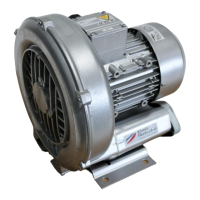
FIGURE 6-1 – ADAPTOR PLATE
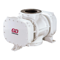
FIGURE 6-2 – ADAPTOR PLATE
Illustrations for Disassembly Instructions are taken from various sizes of CycloBlower. Minor
variations in construction of some parts need cause no concern.
1. Provide adaptor plate, Figure 6-1, for pulling the gear hub (9), and for installation gate rotor
bearings (29, 32).
Numbers in parentheses ( ) refer to key numbers in assembly drawings on pages 31 & 32
2. Provide adaptor plate FIGURE 6-2, for pulling pinion gear (7) and for installation of the main
rotor bearings (30, 31).
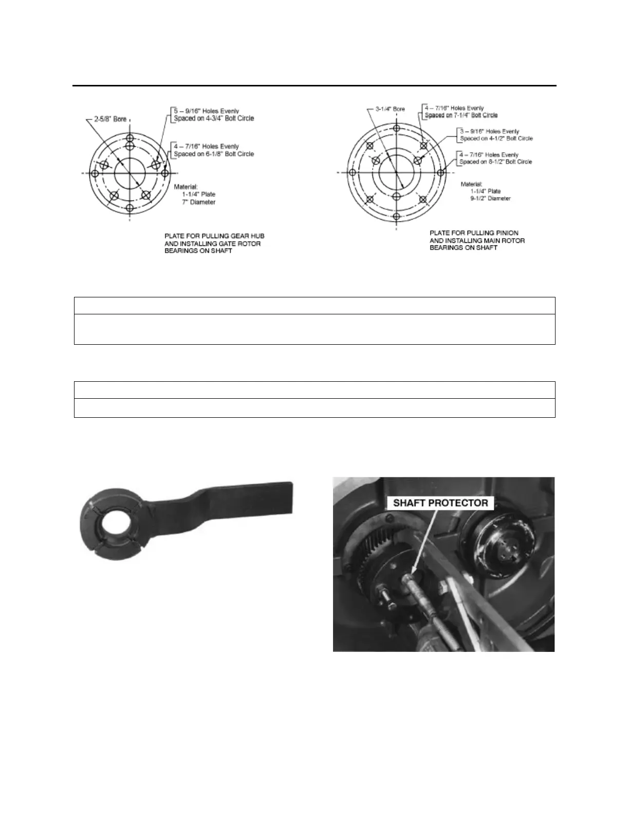
FIGURE 6-3– SPANNER WRENCH
FIGURE 6-4 – ADAPTOR PLATES
 Loading...