13-10-615 Page 28
When the relief valve opens, a stream of high velocity air is released, resulting
in a high noise level and possible discharge of accumulated dirt or other debris.
Always wear eye and ear protection and stand clear of the discharge port when
testing the relief valve to prevent injury.
Never paint, lubricate or alter a relief valve. Do not plug vent or restrict
discharge.
Operation of the unit with improper relief valve setting can result in severe
personal injury or machine damage. Ensure properly set valves are installed
and maintained.
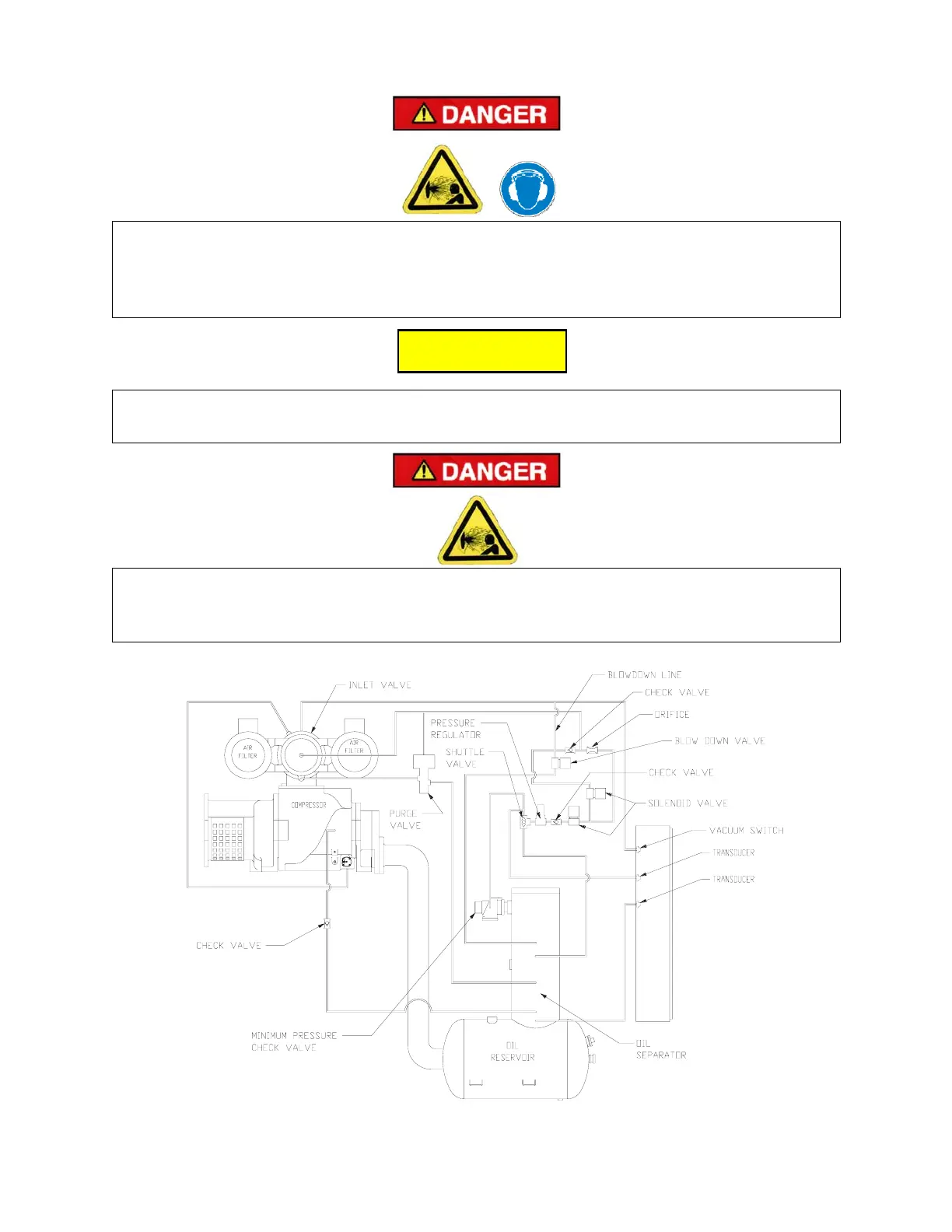
Figure 4-1 – SCHEMATIC TUBING DIAGRAM
205EAU797-
(Ref. Drawing)
C
C
C
A
A
A
U
U
U
T
T
T
I
I
I
O
O
O
N
N
N