13-9-653 Page 8
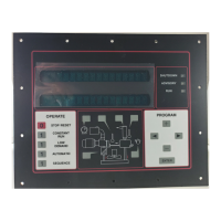
4. In the top line, "LAG START DELAY" is displayed. The bottom line will indicate a number in the range of 1 to
600 seconds. It is factory set at 30. This is the length of time this machine will wait before starting when the
pressure drops below the reset point. This delay period begins when a previous member of the system is
loaded. This should be set to the same value for all sequenced units. Its setting will depend on the amount of air
storage volume in the system. Too small a number will result in more compressors being started than is
necessary to satisfy demand.
5. The controller displays "BAUD RATE" on the top line, and a selection between "1200" or "9600" on the lower
line. The controller can operate at either speed. All units in the system must be set the same. Select the
desired value, and press [ENTER].
6. This completes the sequence adjustments. The controller will return to the main adjustments menu.
Configuration Adjustments
1. In the top line, "HI SYS PRES LIM" is displayed. The bottom line will indicate a value that is factory set 20 - 25
PSI above the nameplate. This is the pressure that will cause a shutdown if exceeded due to a malfunction such
as a stuck inlet valve or broken control line. This should be set at or slightly below the rating of the pressure
relief valve. The controller will attempt a number of actions as it approaches to prevent the pressure from
reaching this limit.
NOTICE
The controller will automatically adjust the set and reset pressure as required, if this limit is
lowered.
2. In the top line, "REMOVE SYS PRESS" is displayed. The bottom line displays the current pressure being
sensed at the package discharge. At this point, steps must be taken to ensure that system pressure is, in fact,
zero psig. Remove the pressure line to the system pressure transducer. Pressing [ENTER] will now cause the
controller to calibrate the transducer output to zero PSIG. Obviously, pressure measurement errors will be
encountered if 'zeroing' is done with pressure at the transducer. If large errors are detected, the controller will
demand that the transducer be checked.
3. In the top line, "REMOVE RES PRESS" is displayed. The bottom line displays the current pressure being
sensed in the reservoir. The reservoir pressure transducer may now be 'zeroed' by following the steps outlined
in step 2 above.
4. In the top line, "AIREND TYPE" is displayed. The bottom line displays the current selection. Set as appropriate
for the compressor.
5. "MOTOR SFA" is displayed on the top line. This should normally be set for either the motor nameplate service
factor amps (SFA, if given) or for the motor nameplate full load amps (FLA) times the motor nameplate service
factor (SF). It may be set lower, if desired. Refer to other features, later in this section, for additional details. If
current monitoring is not installed, set this to zero (0) to disable current monitoring.
6. This completes the configuration adjustments. The controller will return to the main adjustments menu.
Unit Setup Adjustments
1. In the top line, "OIL CHANGE INTERVAL" is displayed. The bottom line will indicate a time interval of 1000 to
12000 hours. After the machine has run for the programmed setting, an advisory will be displayed, requesting an
oil change. Adjust as appropriate and press [ENTER] to proceed.
2. In the top line, "FILTER CHNG INTERVAL" is displayed. The bottom line will indicate a time interval of 500 to
1000 hours. After the machine has run for the programmed setting, an advisory will be displayed, requesting an
oil filter change. Adjust as desired and press [ENTER] to proceed.
3. In the top line, "OVER TEMP LIMIT" is displayed. The bottom line will indicate 225° F. This is the proper setting
for compressor operation with conventional coolant. It may be set higher for high temperature oils, per the
manufacturer’s instructions. It may be temporarily lowered to verify the function of the temperature shutdown
system.