13-9-653 Page 21
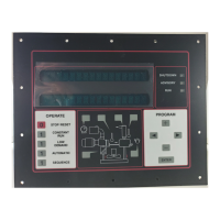
DISPLAY MODES
The normal display indicates the package service pressure, the airend discharge temperature, the total
running hours, and one of the following operating modes. The green run light will be on for any operating
mode, whether the compressor is running or not.
READY The compressor has been stopped by pressing the [STOP/RESET] key.
CON The compressor is operating in the Constant Run mode
LDM The compressor is operating in the Low Demand mode
AUTO The compressor is operating in the Automatic mode
SEQ n The compressor is operating in the Sequence mode
The following alternate displays may be called by pressing a cursor [<] or [>] key
RES PRES The pressure in the oil reservoir
DIF PRES The pressure drop across the separator
RES TMP The temperature at the separator
DIS PRES The pressure at the service connection
DIS TMP The temperature at the airend discharge
BD TMR The time remaining before a blowdown will be allowed
AUTO TMR The time remaining of unloaded motor operation
TOT HRS The total hours of compressor running
LOAD HRS The hours of compressor delivery
The following alternate displays may be called by pressing the [+] or [-] key
MOTOR CURRENT The main motor current in amps
NEXT OIL CHANGE The estimated remaining time until the next recommended change
NEXT OIL FILTER The remaining time until the next recommended filter change
The compressor schematic area keys may be used to select alternate displays.
CLOCK KEY First press shows the total run hourmeter.
CLOCK KEY Second press shows the loaded hourmeter.
CLOCK KEY Third press shows the remaining blowdown time.
CLOCK KEY Fourth press shows the remaining auto time.
DISCH THERM KEY Shows temperature at the compressor discharge.
SEPARATOR KEY First press shows the pressure in the reservoir.
SEPARATOR KEY Second press shows the separator pressure drop.
SEPAR THERM KEY Shows temperature at the reservoir / separator.
OIL CAN KEY Shows estimated remaining time until next recommended oil change.
OIL FILTER KEY Shows remaining time until next recommended oil filter change.
The compressor schematic area has red shutdown and yellow service advisory indicator lights.
AIR FILTER yellow indicates that the filter needs to be changed
DISCH THERM yellow indicates high temperature operation
DISCH THERM red indicates a high temperature shutdown
SEPARATOR yellow indicates the separator needs to be changed
SEPARATOR red indicates a change separator shutdown
SEPAR THERM yellow indicates high temperature operation
SEPAR THERM red indicates a high temperature shutdown
OIL CAN SYMBOL yellow indicates that the oil needs to be changed
FAN MOTOR red indicates a fan motor overload or starter shutdown
OIL FILTER yellow indicates that the filter needs to be changed
DRIVE MOTOR yellow indicates operation with high motor amps
DRIVE MOTOR red indicates a main motor overload or starter shutdown