Do you have a question about the GE Multilin F35 and is the answer not in the manual?
Guides through the initial setup of the relay, including essential precautions and checks.
Emphasizes reviewing all warnings and cautions to prevent injury or damage.
Details steps for inspecting the relay packaging and verifying the model nameplate.
Describes the basic UR design, CPU module, and input/output elements.
Details the firmware design using object-oriented techniques for modularity and scalability.
Covers PC requirements and installation procedures for the EnerVista UR Setup software.
Lists the minimum system requirements for running EnerVista UR Setup software on a PC.
Provides step-by-step instructions for installing the EnerVista UR Setup software.
Explains how to connect to the F35 relay remotely or locally for software access.
Details how to use the Quick Connect feature for RS232 and Ethernet ports for direct communication.
Guides on establishing communication with the F35 relay using the EnerVista UR Setup window.
Explains how to navigate the relay's faceplate keypad and menus for operation.
Explains the process of putting the relay into the "Programmed" state from the factory default.
Recommends setting passwords for security levels (COMMAND and SETTING) to protect access.
Discusses the minimum maintenance required when commissioning the F35 into service.
Introduces the F35 Multiple Feeder Protection System and its key protection functions.
Describes the F35 system's capabilities, including protection, control, metering, and diagnostic features.
Details the available unit types and modules for ordering the F35 relay.
Lists the technical specifications for various protection elements of the F35 relay.
Details operating times, levels, and accuracy for protection elements like overcurrent, undervoltage, etc.
Covers features like FlexLogic™, user-programmable LEDs, displays, and control pushbuttons.
Details oscillography, fault locator, event recorder, and data logger capabilities.
Specifies power supply ranges, internal fuse ratings, and interrupting capacity.
Covers specifications for RS232, RS485, Ethernet (fiber optic and twisted pair) interfaces.
Lists various type tests performed on the relay and their reference standards and test levels.
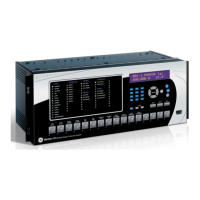
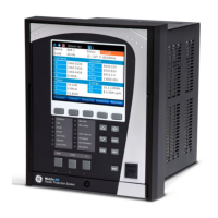
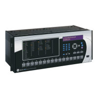
Provides a general description of the F35 hardware, including horizontal and vertical units.
Explains the procedure for safely removing and inserting modules from the relay chassis.
Covers typical wiring configurations for various modules and connections.
Provides instructions and warnings for connecting control power to the relay.
Explains how to connect CT/VT modules, including voltage inputs and current inputs.
Details the terminal connections for digital input/output modules and contact arrangements.
Describes the 9-pin RS232C serial port on the faceplate for PC programming.
Details the communication ports available on the CPU module, including Ethernet options.
Covers the use of type 7 series modules for exchanging digital state information between relays.
Introduces the type 2S and 2T embedded managed switch modules supported by UR-series relays.
Guides on assigning IP/gateway and subnet mask for switch and UR relay operation.
Describes the process for upgrading firmware on UR-2S or UR-2T switch modules.
Introduces the EnerVista UR Setup software as a graphical user interface for relay operations.
Covers advanced features like settings templates and securing FlexLogic™ equations.
Explains how setting file templates simplify configuration and allow locking of settings.
Describes how to secure FlexLogic™ equations to prevent unauthorized viewing or modification.
Explains how to track changes to settings files and determine if security has been compromised.
Details the two types of front panel interfaces: enhanced and standard faceplates.
Explains the meaning of the status and event cause LEDs on the enhanced and standard faceplates.
Details how the F35 can interface with circuit breakers for monitoring and manual operation.
Describes how to enter numerical, enumeration, and alphanumeric data for settings.
Covers settings related to product configuration, including security, display, and communications.
Details password security levels (COMMAND, SETTING) and access supervision settings.
Describes how to clear fault reports, event records, oscillography, and data logger records.
Outlines settings for serial ports (RS232, RS485), network protocols (Ethernet), and Modbus/DNP/IEC protocols.
Explains how to configure fault reports, including source, trigger, and fault location parameters.
Details settings for configuring pushbutton function, text, timing, and LED control.
Covers test settings for verifying relay functionality using simulated conditions.
Explains how to initiate and use the relay's test mode for various procedures.
Covers metering conventions and displays actual values for current, voltage, power, and frequency.
Lists relay directives intended for operations personnel, including virtual inputs and record clearing.
Provides descriptions of major self-test error messages such as MODULE FAILURE and FLEXLOGIC ERROR.
Explains the algorithm for fault type determination and calculation of fault location.
Describes how fault type is determined using sequence components and magnitude checks.
Covers testing procedures for various relay elements, including underfrequency.
Explains techniques for testing underfrequency and overfrequency protection with subtle implications.
Describes the Modbus RTU protocol, including physical and data link layers.
Details the Modbus function codes supported by the relay.
Describes functions for performing operations like reset and clearing records.
Covers password entry for local and remote access to settings and commands.
Provides a detailed list of Modbus memory map addresses for various relay functions.
Covers GSSE and GOOSE services for peer-to-peer data transfer.
Details how to configure the F35 for IEC 61850 using EnerVista UR Setup software.
Provides a procedure for creating an ICD file from a connected F35 or an offline settings file.
Guides on updating the F35 with new configuration from an SCD file using EnerVista UR Setup.
Describes the IEC 60870-5-104 protocol, including interoperability and points list.
Outlines the GE Multilin Relay Warranty, including coverage and limitations.
| Frequency Range | 50/60 Hz |
|---|---|
| Communication Protocols | Modbus, DNP3, IEC 61850 |
| Digital Inputs | 8 |
| Analog Inputs | 4 |
| Digital Outputs | 6 |
| Mounting | Panel mount |
| Enclosure Rating | IP54 |
| Current Rating | 5 A |
| Protection Functions | Overcurrent, Earth Fault, Under/Over Voltage, Frequency Protection |
| Metering | Voltage, Current, Power, Energy, Frequency |
| Display | LCD |