5-172 F35 Multiple Feeder Protection System GE Multilin
5.9 TESTING 5 SETTINGS
5
5.9TESTING 5.9.1 TEST MODE
PATH: SETTINGS ÖØ TESTING Ö TEST MODE
The relay provides test settings to verify that functionality using simulated conditions for contact inputs and outputs. The
test mode is indicated on the relay faceplate by a flashing Test Mode LED indicator.
To initiate the Test mode, the TEST MODE FUNCTION setting must be “Enabled” and the TEST MODE INITIATE setting must be
set to logic 1. In particular:
• To initiate Test Mode through relay settings, set TEST MODE INITIATE to “On”. The test mode starts when the TEST MODE
FUNCTION setting is changed from “Disabled” to “Enabled”.
• To initiate test mode through a user-programmable condition, such as FlexLogic™ operand (pushbutton, digital input,
communication-based input, or a combination of these), set TEST MODE FUNCTION to “Enabled” and set TEST MODE INI-
TIATE to the desired operand. The test mode starts when the selected operand assumes a logic 1 state.
When in test mode, the F35 remains fully operational, allowing for various testing procedures. In particular, the protection
and control elements, FlexLogic™, and communication-based inputs and outputs function normally.
The only difference between the normal operation and the test mode is the behavior of the input and output contacts. The
former can be forced to report as open or closed or remain fully operational; the latter can be forced to open, close, freeze,
or remain fully operational. The response of the digital input and output contacts to the test mode is programmed individu-
ally for each input and output using the force contact inputs and force contact outputs test functions described in the follow-
ing sections.
5.9.2 FORCE CONTACT INPUTS
PATH: SETTINGS ÖØ TESTING ÖØ FORCE CONTACT INPUTS
The relay digital inputs (contact inputs) could be pre-programmed to respond to the test mode in the following ways:
• If set to “Disabled”, the input remains fully operational. It is controlled by the voltage across its input terminals and can
be turned on and off by external circuitry. This value should be selected if a given input must be operational during the
test. This includes, for example, an input initiating the test, or being a part of a user pre-programmed test sequence.
• If set to “Open”, the input is forced to report as opened (Logic 0) for the entire duration of the test mode regardless of
the voltage across the input terminals.
• If set to “Closed”, the input is forced to report as closed (Logic 1) for the entire duration of the test mode regardless of
the voltage across the input terminals.
The force contact inputs feature provides a method of performing checks on the function of all contact inputs. Once
enabled, the relay is placed into test mode, allowing this feature to override the normal function of contact inputs. The Test
Mode LED will be on, indicating that the relay is in test mode. The state of each contact input may be programmed as “Dis-
abled”, “Open”, or “Closed”. All contact input operations return to normal when all settings for this feature are disabled.
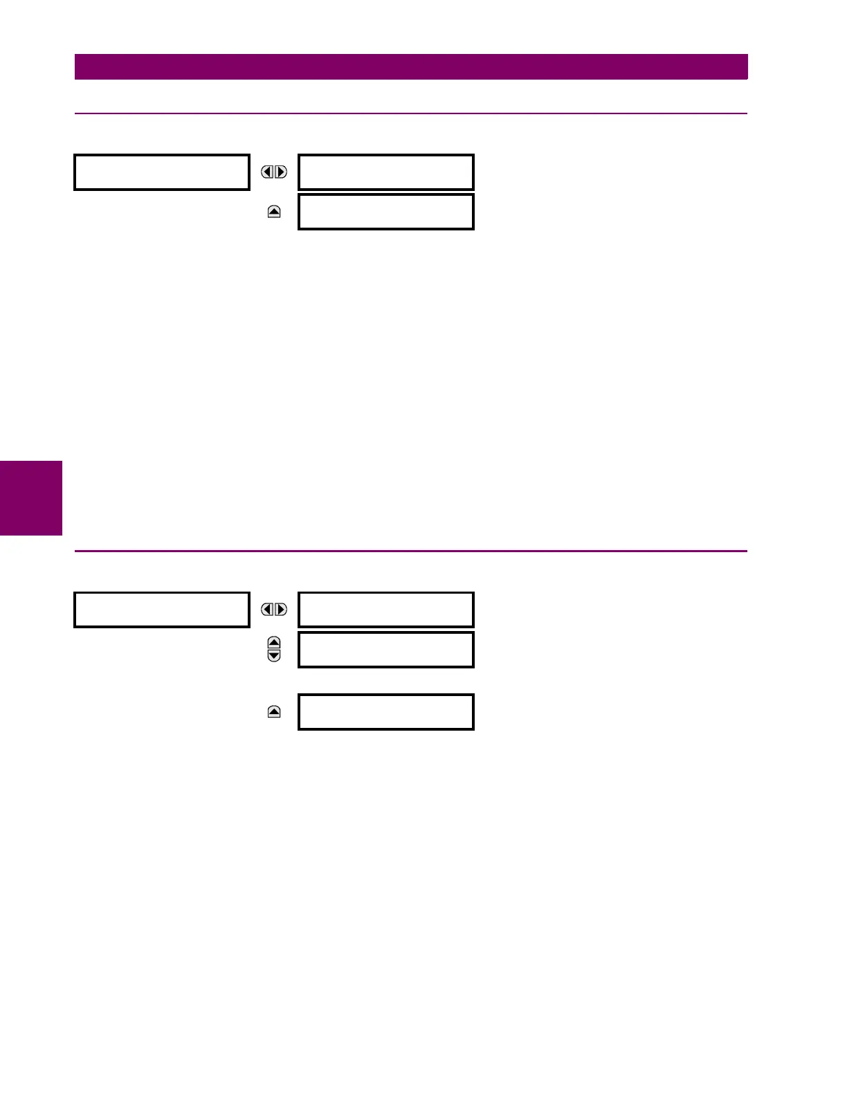
SETTINGS
TESTING
TEST MODE
FUNCTION: Disabled
Range: Disabled, Enabled
MESSAGE
TEST MODE INITIATE:
On
Range: FlexLogic™ operand
FORCE CONTACT
INPUTS
FORCE Cont Ip 1
:Disabled
Range: Disabled, Open, Closed
MESSAGE
FORCE Cont Ip 2
:Disabled
Range: Disabled, Open, Closed
↓
MESSAGE
FORCE Cont Ip xx
:Disabled
Range: Disabled, Open, Closed