GE Multilin F35 Multiple Feeder Protection System 5-103
5 SETTINGS 5.5 GROUPED ELEMENTS
5
5.5GROUPED ELEMENTS 5.5.1 OVERVIEW
Each protection element can be assigned up to six different sets of settings according to setting group designations 1 to 6.
The performance of these elements is defined by the active setting group at a given time. Multiple setting groups allow the
user to conveniently change protection settings for different operating situations (for example, altered power system config-
uration, season of the year, etc.). The active setting group can be preset or selected via the
SETTING GROUPS menu (see the
Control elements section later in this chapter). See also the Introduction to elements section at the beginning of this chap-
ter.
5.5.2 SETTING GROUP
PATH: SETTINGS Ø GROUPED ELEMENTS Ö SETTING GROUP 1(6)
Each of the six setting group menus is identical. Setting group 1 (the default active group) automatically becomes active if
no other group is active (see the Control elements section for additional details).
5.5.3 PHASE CURRENT
a) INVERSE TIME OVERCURRENT CURVE CHARACTERISTICS
The inverse time overcurrent curves used by the time overcurrent elements are the IEEE, IEC, GE Type IAC, and I
2
t stan-
dard curve shapes. This allows for simplified coordination with downstream devices.
If none of these curve shapes is adequate, FlexCurves™ may be used to customize the inverse time curve characteristics.
The definite time curve is also an option that may be appropriate if only simple protection is required.
A time dial multiplier setting allows selection of a multiple of the base curve shape (where the time dial multiplier = 1) with
the curve shape (
CURVE) setting. Unlike the electromechanical time dial equivalent, operate times are directly proportional
to the time multiplier (TD MULTIPLIER) setting value. For example, all times for a multiplier of 10 are 10 times the multiplier 1
or base curve values. Setting the multiplier to zero results in an instantaneous response to all current levels above pickup.
Time overcurrent time calculations are made with an internal energy capacity memory variable. When this variable indi-
cates that the energy capacity has reached 100%, a time overcurrent element will operate. If less than 100% energy capac-
ity is accumulated in this variable and the current falls below the dropout threshold of 97 to 98% of the pickup value, the
variable must be reduced. Two methods of this resetting operation are available: “Instantaneous” and “Timed”. The “Instan-
taneous” selection is intended for applications with other relays, such as most static relays, which set the energy capacity
directly to zero when the current falls below the reset threshold. The “Timed” selection can be used where the relay must
coordinate with electromechanical relays.
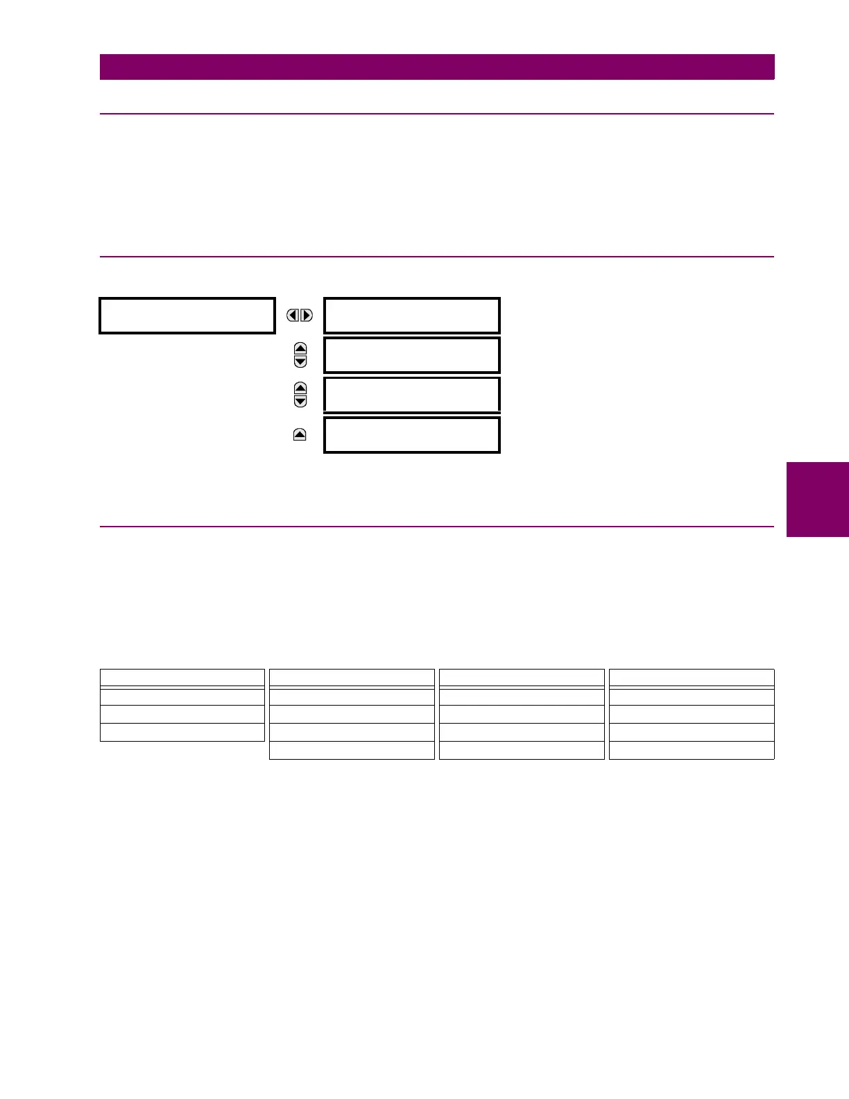
SETTING GROUP 1
PHASE CURRENT
See below.
MESSAGE
NEUTRAL CURRENT
See page 5-111.
MESSAGE
GROUND CURRENT
See page 5-113.
MESSAGE
VOLTAGE ELEMENTS
See page 5-115.
Table 5–11: OVERCURRENT CURVE TYPES
IEEE IEC GE TYPE IAC OTHER
IEEE Extremely Inverse IEC Curve A (BS142) IAC Extremely Inverse I
2
t
IEEE Very Inverse IEC Curve B (BS142) IAC Very Inverse FlexCurves™ A, B, C, and D
IEEE Moderately Inverse IEC Curve C (BS142) IAC Inverse Recloser Curves
IEC Short Inverse IAC Short Inverse Definite Time