GE Multilin F35 Multiple Feeder Protection System 2-1
2 PRODUCT DESCRIPTION 2.1 INTRODUCTION
2
2 PRODUCT DESCRIPTION 2.1INTRODUCTION 2.1.1 OVERVIEW
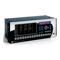
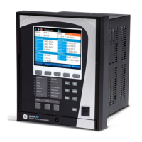
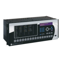
The F35 Multiple Feeder Protection System is a microprocessor based relay designed for the protection of up to five feed-
ers with busbar voltage measurement or up to six feeders without busbar voltage.
Overcurrent and undervoltage protection, breaker recloser, underfrequency, fault diagnostics, and RTU functions are pro-
vided. The F35 provides phase, neutral/ground, instantaneous and time overcurrent protection. The time overcurrent func-
tion provides multiple curve shapes or FlexCurve™ for optimum co-ordination.
Voltage, current, and power metering is built into the relay as a standard feature. Current parameters are available as total
waveform RMS magnitude, or as fundamental frequency only RMS magnitude and angle (phasor). Voltage harmonics and
THD metering are also included with the relay.
Diagnostic features include a sequence of records capable of storing 1024 time-tagged events. The internal clock used for
time-tagging can be synchronized with an IRIG-B signal or via the SNTP protocol over the Ethernet port. This precise time
stamping allows the sequence of events to be determined throughout the system. Events can also be programmed (via
FlexLogic™ equations) to trigger oscillography data capture which may be set to record the measured parameters before
and after the event for viewing on a personal computer (PC). These tools significantly reduce troubleshooting time and sim-
plify report generation in the event of a system fault.
A faceplate RS232 port may be used to connect to a PC for the programming of settings and the monitoring of actual val-
ues. A variety of communications modules are available. Two rear RS485 ports allow independent access by operating and
engineering staff. All serial ports use the Modbus
®
RTU protocol. The RS485 ports may be connected to system computers
with baud rates up to 115.2 kbps. The RS232 port has a fixed baud rate of 19.2 kbps. Optional communications modules
include a 10Base-F Ethernet interface which can be used to provide fast, reliable communications in noisy environments.
Another option provides two 10Base-F fiber optic ports for redundancy. The Ethernet port supports IEC 61850, Modbus
®
/
TCP, and TFTP protocols, and allows access to the relay via any standard web browser (F35 web pages). The IEC 60870-
5-104 protocol is supported on the Ethernet port. DNP 3.0 and IEC 60870-5-104 cannot be enabled at the same time.
The F35 IEDs use flash memory technology which allows field upgrading as new features are added. The following Single
line diagram illustrates the relay functionality using ANSI (American National Standards Institute) device numbers.
Table 2–1: ANSI DEVICE NUMBERS AND FUNCTIONS
DEVICE
NUMBER
FUNCTION DEVICE
NUMBER
FUNCTION
27P Phase undervoltage 51N (up to 6) Neutral time overcurrent
27X Auxiliary undervoltage 51P (up to 6) Phase time overcurrent
50DD Disturbance detector 52 AC circuit breaker
50G (up to 12) Ground instantaneous overcurrent 59N Neutral overvoltage
50N (up to 12) Neutral instantaneous overcurrent 59X Auxiliary overvoltage
50P (up to 12) Phase instantaneous overcurrent 79 (up to 6) Autoreclose
51G (up to 6) Ground time overcurrent 81 (up to 6) Underfrequency