1200C-2000C Fire Alarm Control Panel, Repeater, and Black Box Installation Manual 5
Connecting the LC1502 loop module
The LC1502 loop module allows for the connection of up to two Class A loops or up to
four Class B loops.
The maximum number of loop modules that can be installed will depend on the
control panel model – see “Appendix C: Maximum zones and loops” on page 38 for
more information.
A calculation should be performed for each loop to ensure that the minimum
required loop voltage is maintained for the expected load conditions.
The LC1502 module is located in the cabinet box, between the PS1200N module and
the SD2000 (or VDS2000) module.
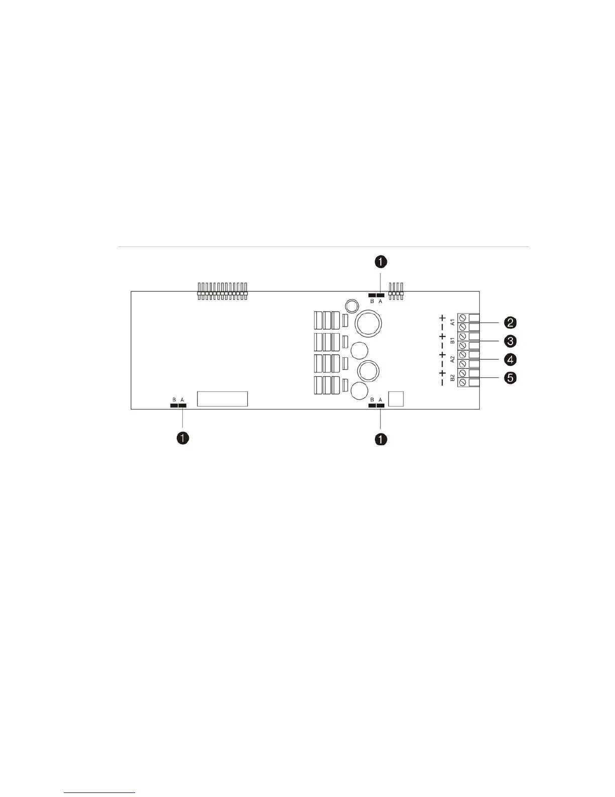
Figure 4: LC1502 loop module
1. Loop Class configuration jumpers A and B
2. Class B loop 1 or Class A loop 1 out
3. Class B loop 2 or Class A loop 1 return
4. Class B loop 3 or Class A loop 2 out
5. Class B loop 4 or Class A loop 2 return
Note: For EN 54 compliance an isolator must be installed after every 32 devices.
Loop Class configuration
Configure the loop Class using jumpers A and B on the loop module (Figure 4 above).
All three A/
B jumpers must be configured for each loop module. When more than one
loop module is installed jumper configuration must be the same for all modules.
• Select jumper A for up to two Class A loops for each loop module
• Select jumper B for up to four Class B loops for each loop module
 Loading...


