7-4 469 Motor Management Relay GE Power Management
7.2 HARDWARE FUNCTIONAL TESTING 7 TESTING
7
7.2.4 GE POWER MANAGEMENT 50:0.025 GROUND ACCURACY TEST
The 469 specification for GE Power Management 50:0.025 ground current input accuracy is
±
0.5% of CT rated
primary (25 A). Perform the steps below to verify accuracy.
1. Alter the following setpoint:
S2 SYSTEM SETUP\CURRENT SENSING\GROUND CT: 50:0.025
2. Measured values should be
±
0.125 A. Inject the values shown in the table below either as primary values
into a GE Power Management 50:0.025 Core Balance CT or as secondary values that simulate the core
balance CT. Verify accuracy of the measured values. View the measured values in:
A2 METERING DATA\CURRENT METERING
7.2.5 RTD ACCURACY TEST
The 469 specification for RTD input accuracy is
±
2
°
. Perform the steps below to verify accuracy.
1. Alter the following setpoints:
S8 RTD TEMPERATURE\RTD TYPE\STATOR RTD TYPE: 100 ohm Platinum (select desired type)
S8 RTD TEMPERATURE\RTD #1\RTD #1 APPLICATION: Stator (repeat for RTDs 2 to 12)
2. Measured values should be
±
2
°
C or ±4°F. Alter the resistances applied to the RTD inputs as per the table
below to simulate RTDs and verify accuracy of the measured values. View the measured values in:
A2 METERING DATA\TEMPERATURE
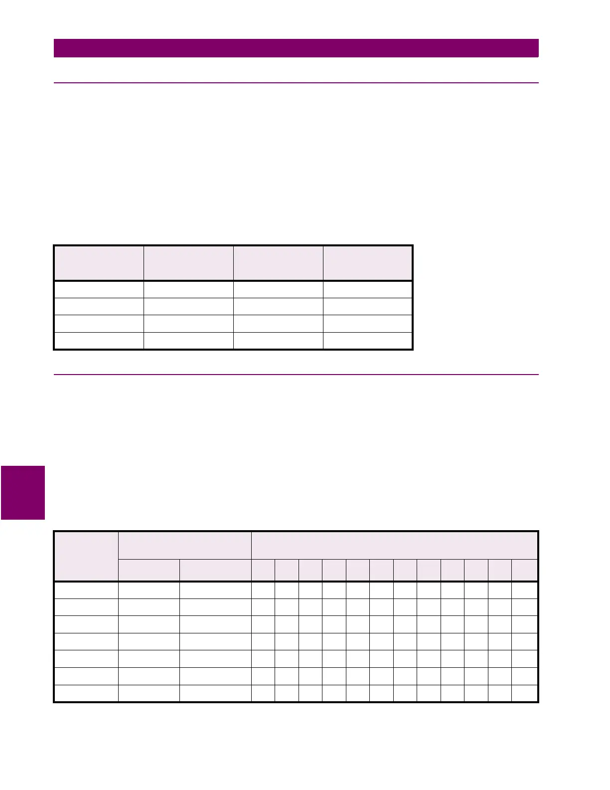
Table 7–5: 50:0.025 CT GROUND CURRENT TEST
PRIMARY
INJECTED
CURRENT
SECONDARY
INJECTED
CURRENT
EXPECTED
CURRENT
READING
MEASURED
GROUND
CURRENT
0.25 A 0.125 mA 0.25 A
1 A 0.5 mA 1.00 A
10 A 5 mA 10.00 A
25 A 12.5 mA 25.00 A
Table 7–6: 100
Ω
PLATINUM TEST
APPLIED
RESISTANCE
100
Ω
PLATINUM
EXPECTED RTD
TEMPERATURE READING
MEASURED RTD TEMPERATURE
SELECT ONE: ____(
°
C ) ____(
°
F )
° CELSIUS ° FAHRENHEIT
1 2 3 4 5 6 7 8 9 10 11 12
80.31 Ω –50°C –58°F
100.00 Ω 0°C 32°F
119.39 Ω 50°C 122°F
138.50 Ω 100°C 212°F
157.32 Ω 150°C 302°F
175.84 Ω 200°C 392°F
194.08 Ω 250°C 482°F

 Loading...


