7-12 469 Motor Management Relay GE Power Management
7.3 ADDITIONAL FUNCTIONAL TESTING 7 TESTING
7
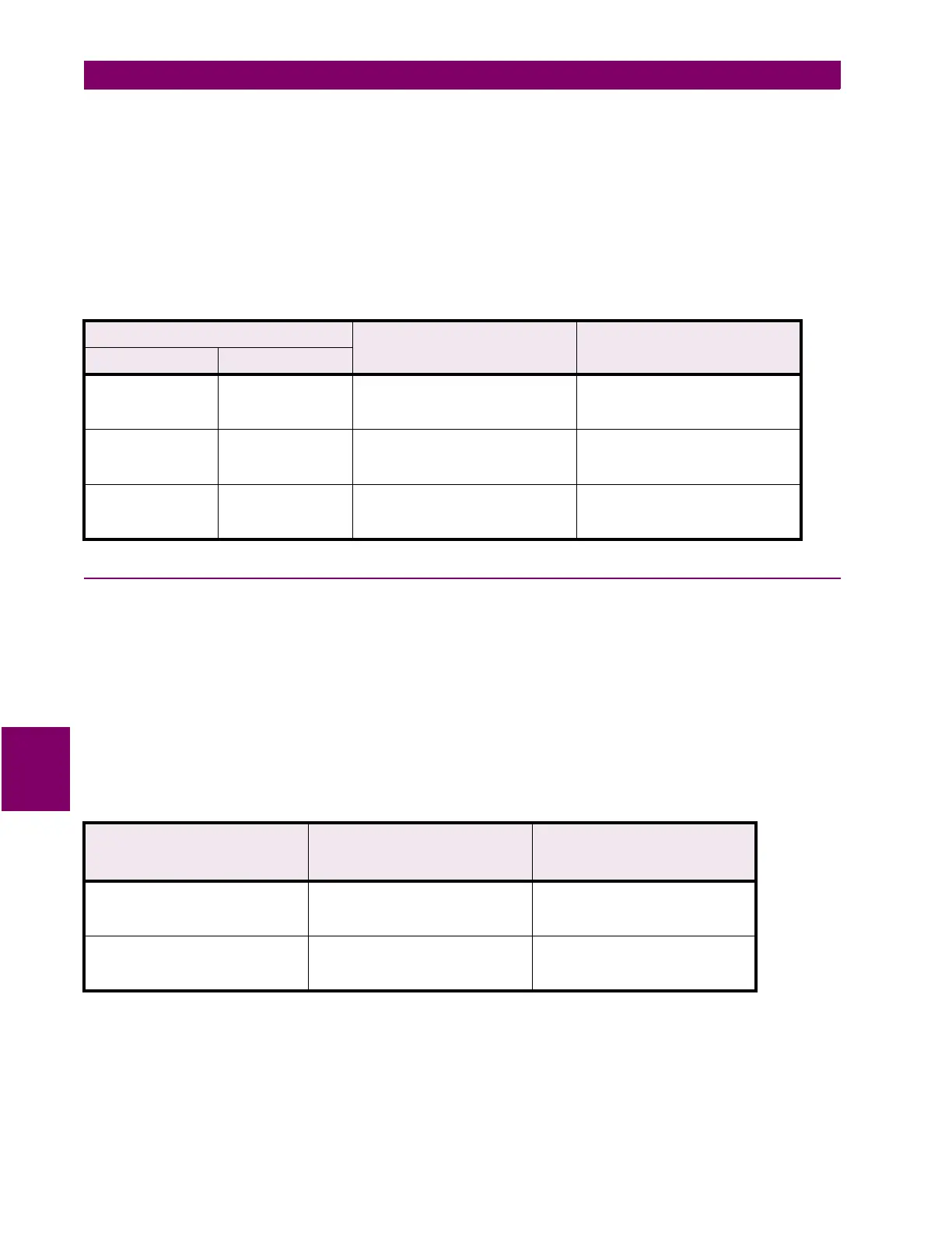
The 469 specification for unbalance accuracy is
±
2%. Perform the steps below to verify accuracy.
1. Alter the following setpoints:
S2 SYSTEM SETUP\CURRENT SENSING\PHASE CT PRIMARY: 1000A
S2 SYSTEM SETUP\CURRENT SENSING\MOTOR FULL LOAD AMPS FLA: 1000A
2. Inject the values shown in the table below and verify accuracy of the measured values. View the measured
values in:
A2 METERING DATA\CURRENT METERING
7.3.4 VOLTAGE PHASE REVERSAL TEST
The 469 can detect voltage phase rotation and protect against phase reversal. To test the phase reversal ele-
ment, perform the following steps:
1. Alter the following setpoints:
S2 SYSTEM SETUP\VOLTAGE SENSING\VT CONNECTION TYPE: Wye or Delta
S2 SYSTEM SETUP\POWER SYSTEM\SYSTEM PHASE SEQUENCE: ABC
S9 VOLTAGE ELEMENTS\PHASE REVERSAL\PHASE REVERSAL TRIP: Latched
S9 VOLTAGE ELEMENTS\PHASE REVERSAL\ASSIGN TRIP RELAYS: Trip
2. Apply voltages as per the table below. Verify the 469 operation on voltage phase reversal.
Table 7–16: CURRENT UNBALANCE TEST
INJECTED CURRENT EXPECTED UNBALANCE
LEVEL
MEASURED UNBALANCE
LEVEL
1 A UNIT 5 A UNIT
Ia = 0.78 A ∠0°
Ib = 1 A ∠247°
Ic = 1 A ∠113°
Ia = 3.9 A ∠0°
Ib = 5 A ∠247°
Ic = 5 A ∠113°
14%
Ia = 1.56 A ∠0°
Ib = 2 A ∠247°
Ic = 2 A ∠113°
Ia = 7.8 A ∠0°
Ib = 10 A ∠247°
Ic = 10 A ∠113°
15%
Ia = 0.39 A ∠0°
Ib = 0.5 A ∠247°
Ic = 0.5 A ∠113°
Ia = 1.95 A ∠0°
Ib = 2.5 A ∠247°
Ic = 2.5 A ∠113°
7%
Table 7–17: VOLTAGE PHASE REVERSAL TEST
APPLIED VOLTAGE EXPECTED RESULT
8
NO TRIP
4
PHASE REVERSAL TRIP
OBSERVED RESULT
8
NO TRIP
4
PHASE REVERSAL TRIP
Va = 120 V ∠0°
Vb = 120 V ∠120°
Vc = 120 V ∠240°
8
Va = 120 V ∠0°
Vb = 120 V ∠240°
Vc = 120 V ∠120°
4

 Loading...


