GE Power Management 469 Motor Management Relay 7-7
7 TESTING 7.2 HARDWARE FUNCTIONAL TESTING
7
3. Verify the ammeter readings as well as the measured analog input readings. For the purposes of testing,
the analog input is fed in from the analog output (see Figure 7–1: SECONDARY INJECTION TEST
SETUP). View the measured values in:
A2 METERING DATA\ANALOG INPUTS
b) 0-1 mA
1. Alter the following setpoints:
S12 ANALOG I/O\ANALOG INPUT1\ANALOG INPUT1: 0-1 mA
S12 ANALOG I/O\ANALOG INPUT1\ANALOG INPUT1 MINIMUM: 0
S12 ANALOG I/O\ANALOG INPUT1\ANALOG INPUT1 MAXIMUM: 1000 (repeat for analog inputs 2 to 4)
2. Analog output values should be
±
0.01 mA on the ammeter. Measured analog input values should be
±
10
units. Force the analog outputs using the following setpoints:
S13 TESTING\TEST ANALOG OUTPUT\FORCE ANALOG OUTPUTS FUNCTION: Enabled
S13 TESTING\TEST ANALOG OUTPUT\ANALOG OUTPUT 1 FORCED VALUE: 0%
(enter desired percent, repeats for analog output 2-4)
3. Verify the ammeter readings as well as the measured analog input readings. View the measured values in:
A2 METERING DATA\ANALOG INPUTS
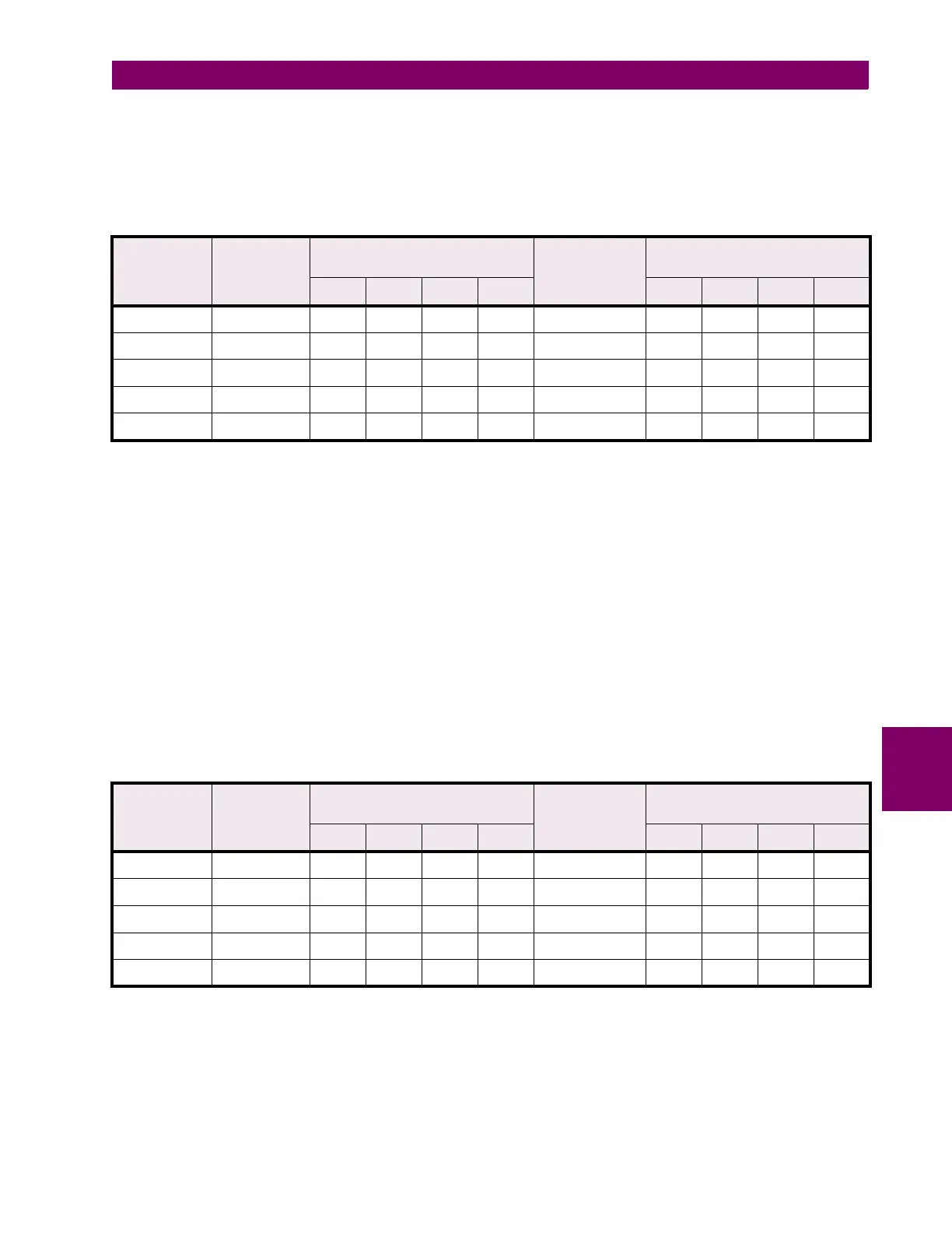
Table 7–11: ANALOG I/O TEST 4-20 mA
ANALOG
OUTPUT
FORCE
VALUE
EXPECTED
AMMETER
READING
MEASURED AMMETER
READING (mA)
EXPECTED
ANALOG
INPUT
READING
MEASURED ANALOG INPUT
READING (units)
1 2 3 4 1 2 3 4
0% 4 mA 0 mA
25% 8 mA 250 mA
50% 12 mA 500 mA
75% 16 mA 750 mA
100% 20 mA 1000 mA
Table 7–12: ANALOG I/O TEST 0-1 mA
ANALOG
OUTPUT
FORCE
VALUE
EXPECTED
AMMETER
READING
MEASURED AMMETER
READING (mA)
EXPECTED
ANALOG
INPUT
READING
MEASURED ANALOG INPUT
READING (units)
1 2 3 4 1 2 3 4
0% 0 mA 0 mA
25% 0.25 mA 250 mA
50% 0.50 mA 500 mA
75% 0.75 mA 750 mA
100% 1.00 mA 1000 mA

 Loading...


