B-2 469 Motor Management Relay GE Power Management
B.1 TWO-PHASE CT CONFIGURATION APPENDIX B
B
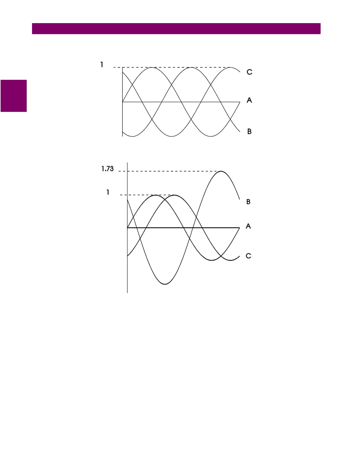
To illustrate the point further, the diagram below shows how the current in phases A and C sum up to create
phase 'B'.
Once again, if the polarity of one of the phases is out by 180°, the magnitude of the resulting vector on a bal-
anced system will be out by a factor of 1.73.
On a three wire supply, this configuration will always work and unbalance will be detected properly. In the event
of a single phase, there will always be a large unbalance present at the interposing CTs of the relay. If for
example phase A was lost, phase A would read zero while phases B and C would both read the magnitude of
phase C. If on the other hand, phase B was lost, at the supply, phase A would be 180° out-of-phase with phase
C and the vector addition would equal zero at phase B.

 Loading...


