GE Power Management 469 Motor Management Relay 4-39
4 SETPOINT PROGRAMMING 4.6 S5 THERMAL MODEL
4
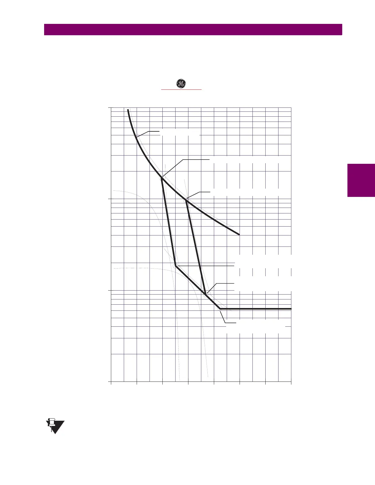
The 469 takes the information provided and create protection curves for any voltage between the minimum
and 100%. For values above the voltage in question, the 469 extrapolates the safe stall protection curve to
110% voltage. This current level is calculated by taking the locked rotor current @ 100% voltage and multiply-
ing by 1.10. For trip times above the 110% current level, the trip time of 110% will be used. (see figure below).
Figure 4–13: VOLTAGE DEPENDENT OVERLOAD PROTECTION CURVES
The safe stall curve is in reality a series of safe stall points for different voltages. For a given
voltage, there can only be one value of stall current and therefore, only one safe stall time.
1
123 456 78
2
3
4
5
6
7
8
9
10
20
30
40
50
60
70
80
90
100
HIGH INERTIA LOAD OVERLOAD CURVES
8800 HP, 13.2 kV, REACTOR COOLANT PUMP
TIME TO TRIP (SECONDS)
MULTIPLES OF FULL LOAD AMPS
200
300
400
500
600
700
800
900
1000
Acceleration Intersect @ 80%V
Custom Curve
Acceleration Intersect @ 100%V
Safe Stall Time @ 80%V,
80%V Stall Current
Safe Stall Time @ 100%V,
100%V Stall Current
Safe Stall Points
Extrapolated to 110%V
806824A3.CDR
GE Power ManagementGE Power Management
NOTE

 Loading...


