CHAPTER 5: SETTINGS
469 MOTOR MANAGEMENT RELAY – INSTRUCTION MANUAL 5–27
These settings apply only if the INPUT 1(4) FUNCTION is “Remote Trip”.
Once the Remote Trip function is chosen for one of the assignable digital inputs, the
settings messages shown here will follow the assignment message. A trip relay may be
selected and the name of the trip may be altered. A contact closure on the digital input
assigned as Remote Trip will cause a trip within 100 ms with the name that has been
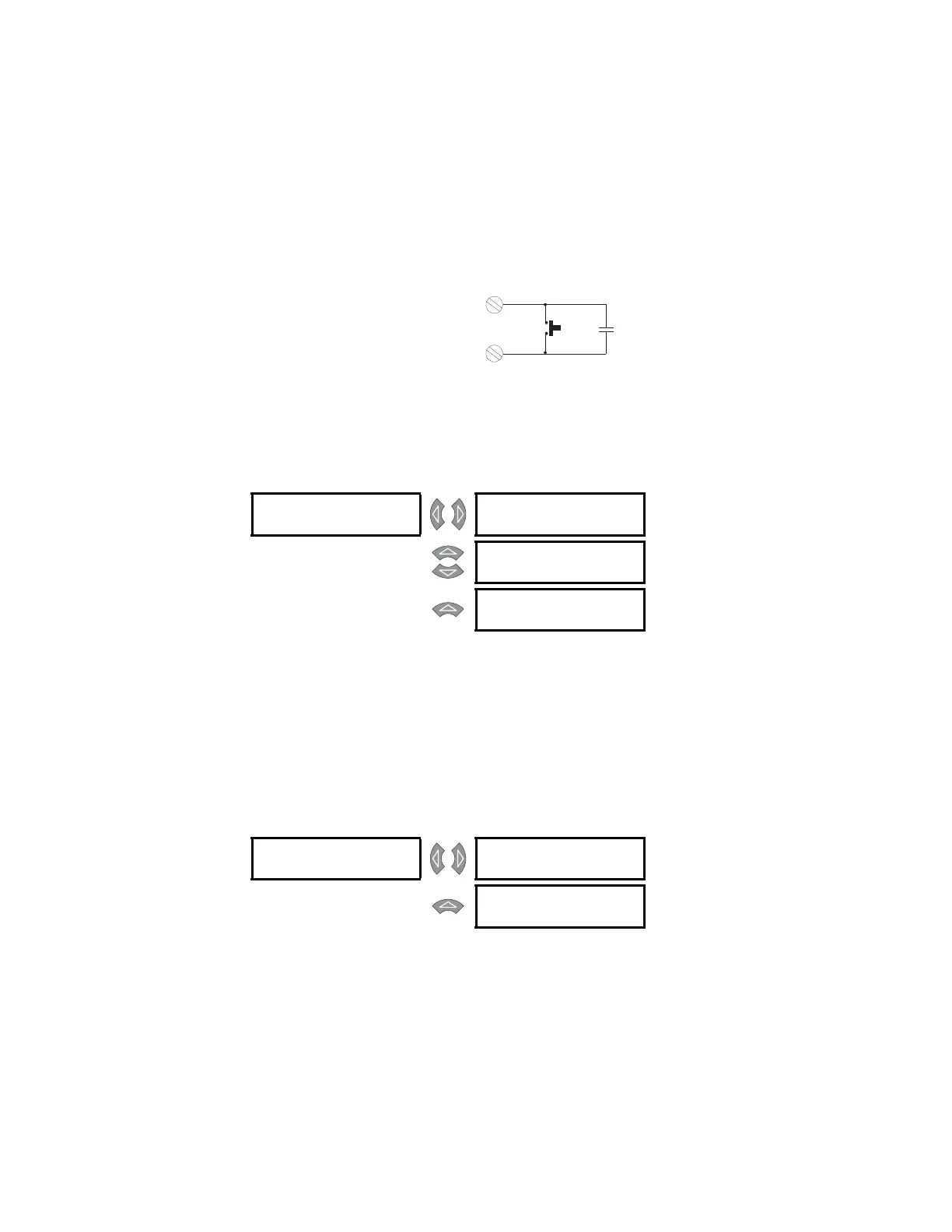
chosen. Multiple sources may be used to trigger a remote trip by paralleling inputs.
FIGURE 5–4: Remote Alarm/Trip from Multiple Sources
Speed Switch Trip
PATH: SETTINGS ZV S3 DIGITAL INPUTS ZV ASSIGNABLE INPUT 1(4)
These settings apply only if the INPUT 1(4) FUNCTION is “Speed Switch Trip”.
When this function is assigned to a digital input, the following will occur. When a transition
from stopped to start is detected a timer will be loaded with the delay programmed. If that
delay expires before a contact closure is detected, a trip will occur. Once the motor is
stopped, the scheme is reset.
Load Shed Trip
PATH: SETTINGS ZV S3 DIGITAL INPUTS ZV ASSIGNABLE INPUT 1(4)
These settings apply only if the INPUT 1(4) FUNCTION is “Load Shed Trip”.
Once the load shed trip function is chosen for one of the assignable digital inputs, the
settings messages shown here will follow the assignment message. A trip relay may be
selected. A contact closure on the switch input assigned as load shed trip will cause a trip
within 100 ms.
808716A1.CDR
REMOTE
PUSH-BUTTON
469 DigitalInput
Dry contact from other device
ASSIGNABLE [
INPUT 1 FUNCTION:
Speed Switch Trip
Range: See above.
MESSAGE
ASSIGN TRIP
RELAYS:
Range: Trip, Trip & Auxiliary2, Trip &
Aux2 & Aux3, Trip & Auxiliary3
MESSAGE
SPEED SWITCH TRIP
TIME DELAY: 5.0 s
Range: 1.0 to 250.0 s in steps of 0.1
ASSIGNABLE [
INPUT 1 FUNCTION:
Load Shed Trip
Range: See above
MESSAGE
ASSIGN TRIP
RELAYS:
Range: Trip, Trip & Auxiliary2, Trip &
Aux2 & Aux3, Trip & Auxiliary3