7–14 469 MOTOR MANAGEMENT RELAY – INSTRUCTION MANUAL
CHAPTER 7: TESTING
S2 SYSTEM SETUP ZV VOLTAGE SENSING Z VT CONNECTION TYPE: “Wye” or “Delta”
S2 SYSTEM SETUP ZV POWER SYSTEM ZV SYSTEM PHASE SEQUENCE: “ABC”
S9 VOLTAGE ELEMENTS ZV PHASE REVERSAL Z PHASE REVERSAL TRIP: “Latched”
S9 VOLTAGE ELEMENTS ZV PHASE REVERSAL ZV ASSIGN TRIP RELAYS: “Trip”
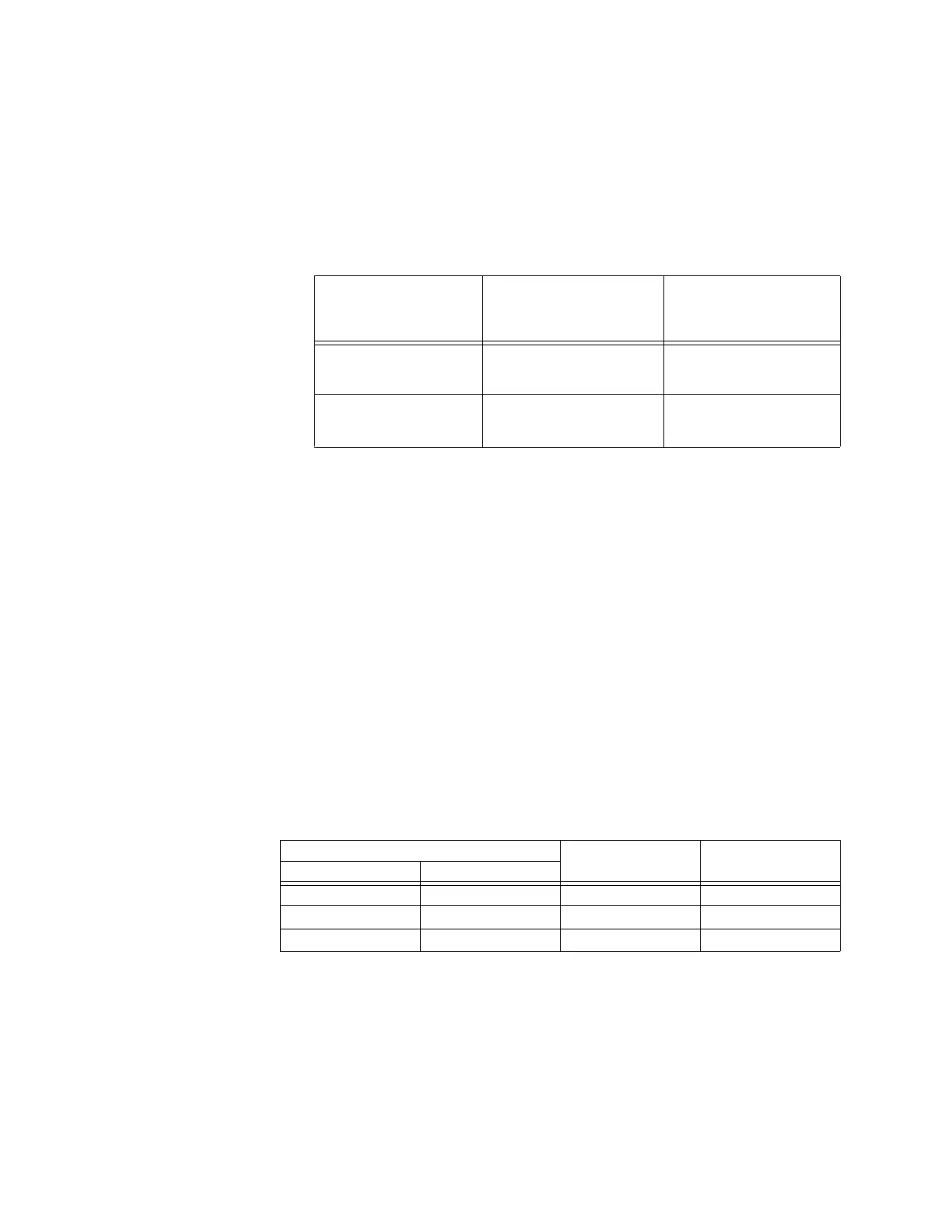
Z Apply voltages as per the table below.
Z Verify the 469 operation on voltage phase reversal.
7.3.5 Short Circuit Test
The 469 specification for short circuit timing is +50 ms. The pickup accuracy is as per the
phase current inputs. Perform the steps below to verify the performance of the short circuit
element.
Z Alter the following settings:
S2 SYSTEM SETUP Z CURRENT SENSING Z PHASE CT PRIMARY: “1000”
S6 CURRENT ELEMENTS Z SHORT CIRCUIT TRIP Z SHORT CIRCUIT TRIP: “On”
S6 CURRENT ELEMENTS Z SHORT CIRCUIT TRIP ZV ASSIGN TRIP RELAYS: “Trip”
S6 CURRENT ELEMENTS Z SHORT CIRCUIT TRIP ZV SHORT CIRCUIT TRIP PICKUP: “5.0 ×
CT”
S6 CURRENT ELEMENTS Z SHORT CIRCUIT TRIP ZV INTENTIONAL S/C DELAY: “0”
Z Inject current as per the table below, resetting the unit after each trip by
pressing the
RESET key, and verify timing accuracy.
Z Pre-trip values may be viewed by pressing
NEXT after each trip.
APPLIED VOLTAGE EXPECTED RESULT
8 NO TRIP
4 PHASE REVERSAL
TRIP
OBSERVED RESULT
8 NO TRIP
4 PHASE REVERSAL
TRIP
Va = 120 V ∠0°
Vb = 120 V ∠120°
Vc = 120 V ∠240°
8
Va = 120 V ∠0°
Vb = 120 V ∠240°
Vc = 120 V ∠120°
4
INJECTED CURRENT EXPECTED TIME
TO TRIP
MEASURED TIME
TO TRIP
5 A UNIT 1 A UNIT
30 A 6 A < 50 ms
40 A 8 A < 50 ms
50 A 10 A < 50 ms