CHAPTER 5: SETTINGS
469 MOTOR MANAGEMENT RELAY – INSTRUCTION MANUAL 5–99
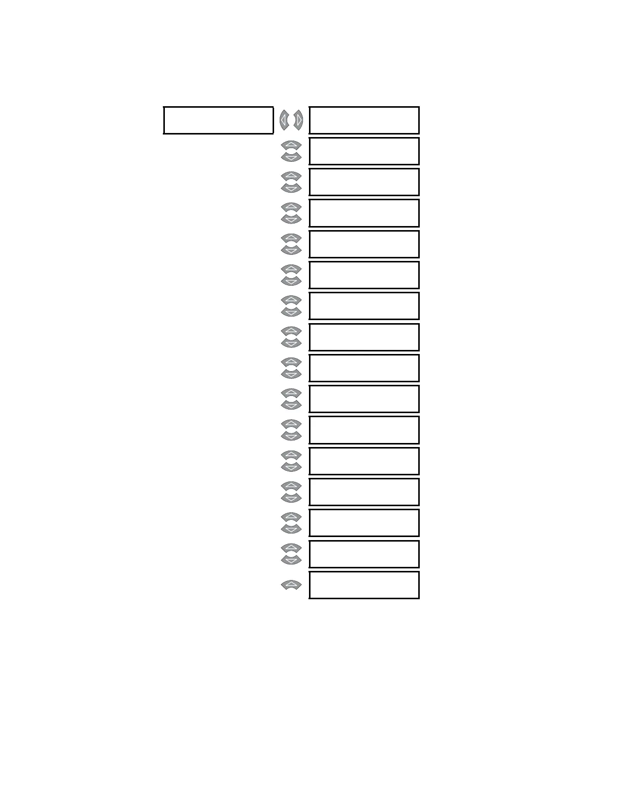
5.14.2 Pre-Fault Setup
PATH: SETTINGS ZV S13 469 TESTING ZV PRE-FAULT SETUP
The values entered under Pre-Fault Values will be substituted for the measured values in
the 469 when the simulation mode is “Simulate Pre-Fault”.
PRE-
FAULT [Z]
PRE-FAULT CURRENT
PHASE A: 0.00 x
Range: 0.00 to 20.00 x CT in steps of
0.01
MESSAGE
PRE-FAULT CURRENT
PHASE B: 0.00 x
Range: 0.00 to 20.00 x CT in steps of
0.01
MESSAGE
PRE-FAULT CURRENT
PHASE C: 0.00 x
Range: 0.00 to 20.00 x CT in steps of
0.01
MESSAGE
PRE-FAULT GROUND
CURRENT: 0.0 A
Range: 0.0 to 5000.0 A in steps of 0.1
MESSAGE
PRE-FAULT VOLT-
AGES
Range: 0.00 to 1.10 x RATED in steps of
0.01
MESSAGE
PRE-FAULT CURRENT
LAGS VOLTAGE: 0°
Range: 0 to 359° in steps of 1
MESSAGE
PRE-FAULT DIFF
AMPS
Range: 0.00 to 1.10 x RATED in steps of
0.01
MESSAGE
PRE-FAULT STATOR
RTD TEMP: 40°C
Range: –50 to 250°C in steps of 1
MESSAGE
PRE-FAULT BEARING
RTD TEMP: 40°C
Range: –50 to 250°C in steps of 1
MESSAGE
PRE-FAULT OTHER
RTD TEMP: 40°C
Range: –50 to 250°C in steps of 1
MESSAGE
PRE-FAULT AMBIENT
RTD TEMP: 40°C
Range: –50 to 250°C in steps of 1
MESSAGE
PRE-FAULT SYSTEM
FREQUENCY: 60.0
Range: 45.0 to 70.0 Hz in steps of 0.1
MESSAGE
PRE-FAULT ANALOG
INPUT 1: 0%
Range: 0 to 100% in steps of 1
MESSAGE
PRE-FAULT ANALOG
INPUT 2: 0%
Range: 0 to 100% in steps of 1
MESSAGE
PRE-FAULT ANALOG
INPUT 3: 0%
Range: 0 to 100% in steps of 1
MESSAGE
PRE-FAULT ANALOG
INPUT 4: 0%
Range: 0 to 100% in steps of 1