CHAPTER 5: SETTINGS
469 MOTOR MANAGEMENT RELAY – INSTRUCTION MANUAL 5–29
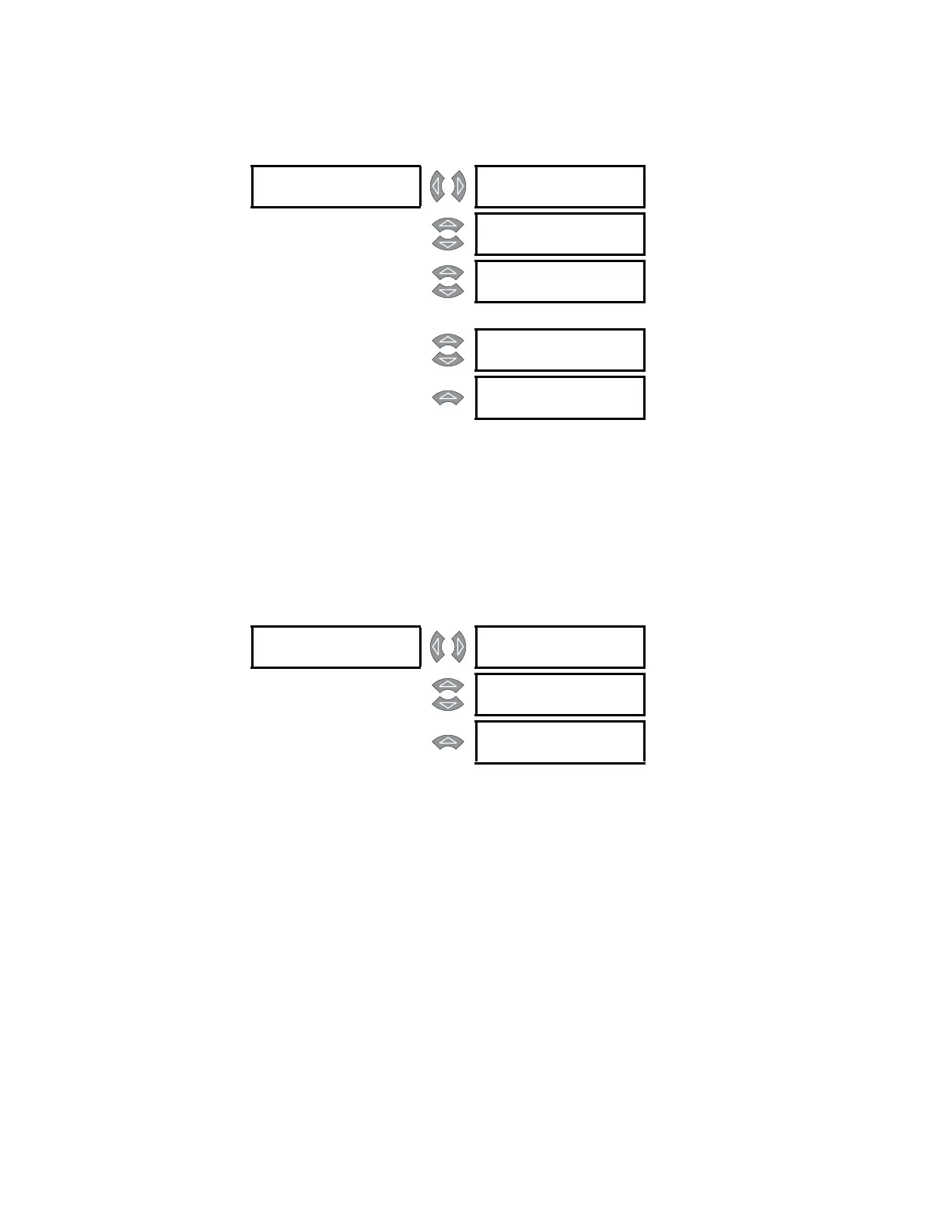
Vibration Switch Alarm
PATH: SETTINGS ZV S3 DIGITAL INPUTS ZV ASSIGNABLE INPUT 1(4)
These settings apply only if the INPUT 1(4) FUNCTION is “Vibration Sw. Alarm”.
Once the Vibration Switch Alarm function is chosen for one of the digital inputs, the
settings messages shown follow the assignment message. When the motor is stopped or
running, the digital input will be monitored. If a closure occurs, an alarm will occur after the
specified delay.
Vibration Switch Trip
PATH: SETTINGS ZV S3 DIGITAL INPUTS ZV ASSIGNABLE INPUT 1(4)
These settings apply only if the INPUT 1(4) FUNCTION is “Pressure Sw. Trip”.
Once Vibration Switch Trip is chosen for a digital input, the settings shown follow the
assignment message. When the motor is stopped or running, the digital input will be
monitored. If a closure occurs, a trip will occur after the specified delay.
ASSIGNABLE [
INPUT 1 FUNCTION:
Vibration Sw
Range: See above
MESSAGE
VIBRATION SWITCH
ALARM: Unlatched
Range: Latched, Unlatched
MESSAGE
ASSIGN ALARM
RELAYS:
Range: Alarm, Alarm & Auxiliary2,
Alarm & Aux2 & Aux3, Alarm &
Auxiliary3, Auxiliary2, Aux2 &
Aux3, Auxiliary3
MESSAGE
VIBRATION SW.
ALARM
Range: 0.1 to 100.0 s in steps of 0.1
MESSAGE
VIBRATION SW.
ALARM
Range: On, Off
ASSIGNABLE [
INPUT 1 FUNCTION:
Vibration Sw Trip
Range: See above
MESSAGE
ASSIGN TRIP
RELAYS:
Range: Trip, Trip & Auxiliary2, Trip &
Aux2 & Aux3, Trip & Auxiliary3
MESSAGE
VIBRATION SW.
TRIP
Range: 0.1 to 100.0 s in steps of 0.1